设计简介
摘 要
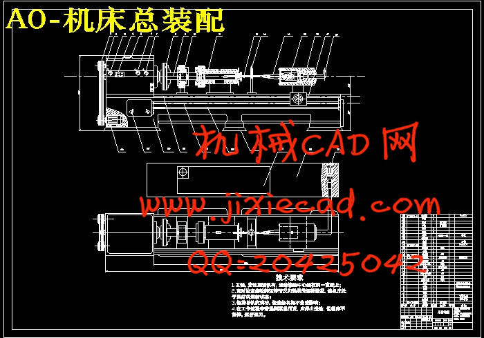
该设计是设计一超声深孔钻床,利用超声震动加工深孔。振动钻削,即在钻头(或工件)正常工作进给的同时,对钻头(或工件)施加某种有规律的振动,使钻头在振动中切削,形成脉冲式的切削力波形,使切削用量按某种规律变化,以达到改善切削效能的目的。根据实际加工的需要,适当选择振动参数(频率v,振幅A以及频率v与工件转速n的比例关系),可以控制切屑的大小和形状,得到满意的切屑,避免切屑堵塞。可提高生产效率几倍到十几倍,提高加工精度1—2级,且加工表面质量也有较大改善。超声振动深孔加工钻床是利用超声振动系统对钻头施加振动,使钻头在振动中切削,使切削用两按规律变化,从而达到改善切削效能的目的。
关键词:超声振动,深孔加工,枪钻车床。
Abstract
This design is designs a supersonic deep hole drilling machine, the use supersonic vibration processes the deep hole. The vibration drills truncates, namely while the drill bit (or work piece) normal work to feed, (or work piece) exerts some kind of orderly vibration to the drill bit, causes the drill bit to cut in the vibration, forms the pulse -like cutting force profile, causes the cutting specifications according to some kind of rule change, achieves the improvement cutting potency the goal。According to the actual processing need, chooses the vibration parameter suitably (frequency v, oscillation amplitude A as well as frequency v with the work piece rotational speed n proportional relationship), may control the scrap the size and the shape, obtains satisfaction scrap, avoids the scrap jamming. May enhance production efficiency several times to several times, enhances the processing precision 1-2 level, also the processing surface quality also has improves greatly.
The ultrasonic vibration deep hole processing drilling machine is the use ultrasonic vibration system to the drill bit infliction vibration, causes the drill bit to cut in the vibration, causes the cutting with two according to the rule change, thus achieves the improvement cutting potency the goal.
Key words: The ultrasonic vibration, the deep hole processing, butts the lathe.
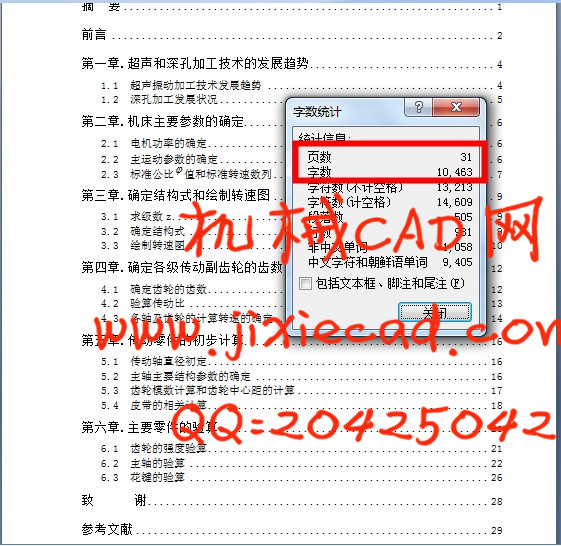
目录
摘 要 1
前言 2
第一章.超声和深孔加工技术的发展趋势 4
1.1 超声振动加工技术发展趋势 4
1.2 深孔加工发展状况 5
第二章.机床主要参数的确定 6
2.1 电机功率的确定 6
2.2 主运动参数的确定 6
2.3 标准公比
第三章.确定结构式和绘制转速图 9
3.1 求级数z 9
3.2 确定结构式 9
3.3 绘制转速图 10
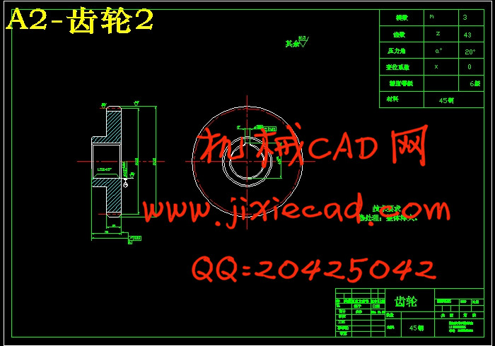
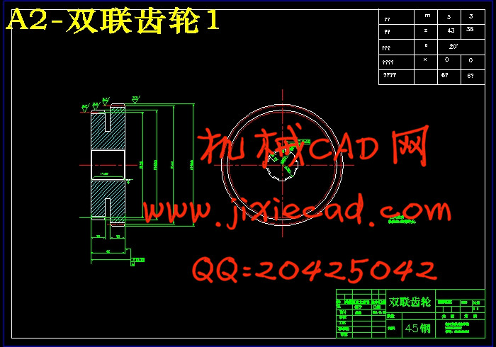
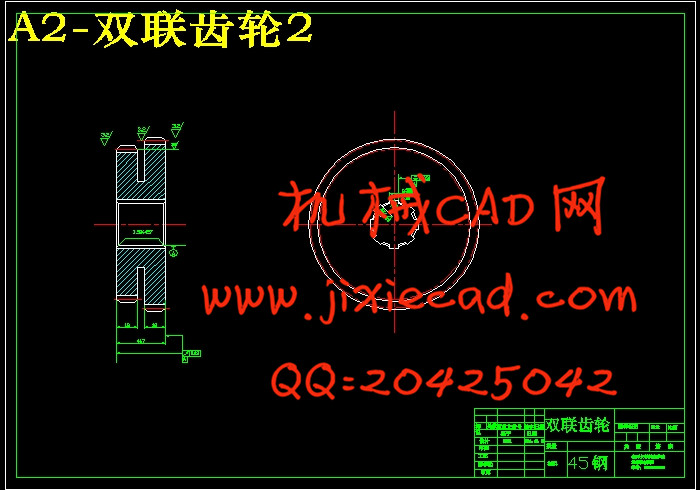
第四章.确定各级传动副齿轮的齿数 12
4.1 确定齿轮的齿数 12
4.2 验算传动比 13
4.3 各轴及齿轮的计算转速的确定 14
第五章.传动零件的初步计算 16
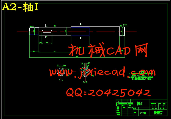
5.1 传动轴直径初定 16
5.2 主轴主要结构参数的确定 16
5.3 齿轮模数计算和齿轮中心距的计算 17
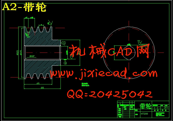
5.4 皮带的相关计算 18
第六章.主要零件的验算 21
6.1 齿轮的强度验算 21
6.2 主轴的验算 22
6.3 花键的验算 26
致 谢 28
参考文献 29
英文文献 30