设计简介
摘 要
设计的轧钢机为400×2型轧钢机,轧辊的直径为400 mm,辊面长650mm.轧制力为100T。轧钢机主要用来为轧制小型线材,采用两辊式工作机座。轧机是实现金属轧制过程的设备。泛指完成轧材生产全过程的装备﹐包括有主要设备﹑辅助设备﹑起重运输设备和附属设备等。但一般所说的轧机往往仅指主要设备。轧钢机的主要设备是由一个主机列组成的。轧钢机的主机列是由原动机,传动装置和执行机构三个基本部分组成的。采用的配置方式为电动机——减速机——分齿箱——轧机。由于轧辊的转向和转速不可逆转,原动机采用造价较底的高速交流主电机。考虑到轧制负荷很不均匀,为了均衡电机负荷,减少电机的容量,在减速机和电动机之间加有飞轮。分齿箱:其用途是传递转矩给工作辊,装在密闭的箱体内。联轴器:轴与轴之间的链接用联轴器。关键词: 轧钢机,分齿箱,飞轮 Abstract
Design of rolling mill is 400 ×2 type rolling mill, roll diameter is 400 mm, long 650mm. rolling force roll surface for100T. Rolling mill for rolling mainly to small wire, uses two rollers type working machine. Rolling mill is the realization of metal rolling equipment. A complete rolling production process equipment, including the main equipment, auxiliary equipment, lifting the transport equipment and ancillary equipment. But the general said mill often refers only to the main equipment. Rolling mill equipment is a major component of the mainframe out. Rolling machine mainframe is composed of a prime mover, transmission device and an actuating mechanism of three basic components. Allocation method used for electric motors -- -- -- mill reducer gear box. The roller to the irreversible and rotational speed, the original motivation for the introduction of the cost of a more rapid exchange of main motor. Taking into account the rolling load is uneven, in order to balance the load of the motor, reduce the electrical capacity, slowdown in the increase between a flywheel and electric motors. Gear box: its purpose is to transmit torque to the work roll, packed in a sealed box body. Coupling: the link between the shaft and the shaft coupling.
Key words:Rolling mill,gear seat,flywheel
Key words:Rolling mill,gear seat,flywheel
目 录
摘 要 IAbstract II
目 录 III
第1章 绪论 1
1.1 轧钢机的定义 1
1.2 轧钢机的标称 1
1.3 轧钢机的用途 2
1.4 小型轧钢机的主机列 2
1.5 轧钢机的发展 5
第2章 设计方案的确定 6
2.1传动方案的确定 6
2.1.1机械传动系统拟定的一般原则 6
2.1.2确定最终传动方案 7
2.2 确定各传动机构的传动效率 7
第3章 电动机的选择 8
3.1电动机功率的计算推演 8
3.2确定电动机具体型号 8
第4章 联轴器的选择 11
第5章 减速器的选择 19
5.1传动比的计算 19
5.2减速器的型号和各项参数的确定 19
5.3减速器的特点与破坏形式 20
5.4主减速机的结构 21
5.5主减速器的润滑及防护措施 21
5.6齿轮的材料和热处理 22
5.7减速器的工作状态分析 22
第6章 分轴器的设计 23
6.1齿轮传动 23
6.2齿轮轴的校核 23
6.2.1选择材料为45钢,经调质处理 23
6.2.2求出轴上的转矩
6.2.3求作用在齿轮上的力 23
6.2.4确定各段轴的轴径 24
6.2.5求支反力 24
6.2.6作弯矩图和转矩图 24
6.2.4轴的校核 27
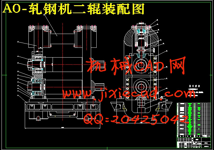
第7章 轧钢机工作机座的设计 29
7.1工作机座的选择 29
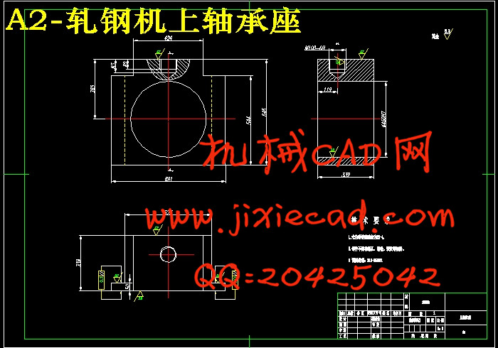
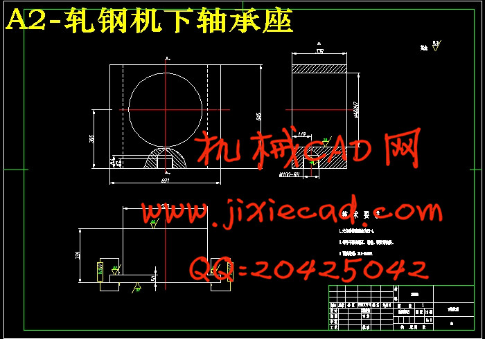
7.2轧辊与轧辊轴承的设计 29
7.3轧辊调整装置的设计 32
7.4压下装置的选择 34
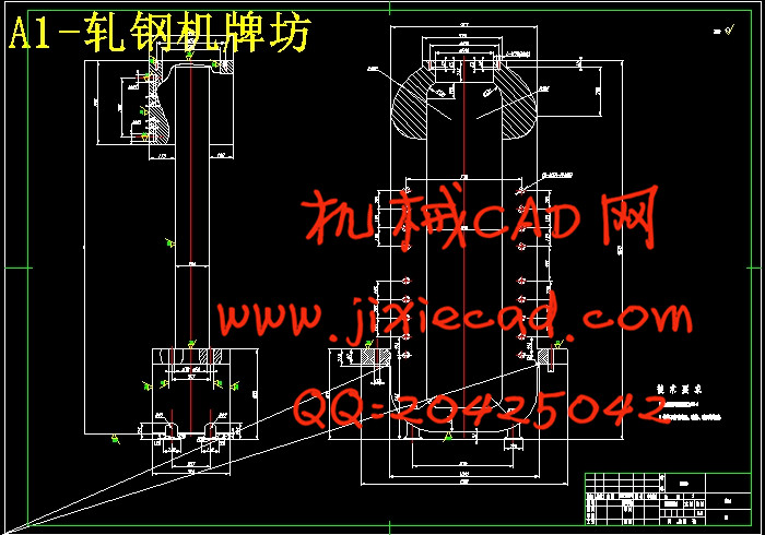
7.5机架的设计 35