设计简介
摘 要
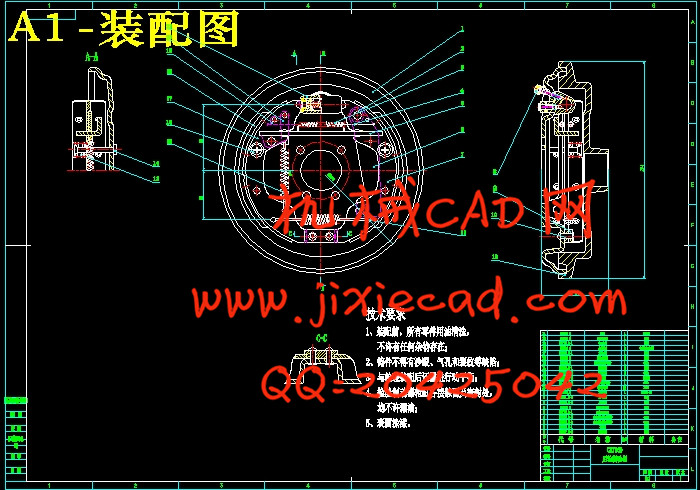
制动器是使机械中的运动件停止或减速的机械零件。汽车的制动性是汽车的主要性能之一。任何一套制动系统均由制动器和制动驱动机构组成。制动器是制动系统中用以产生阻碍车辆运动或运动趋势的力的部件,本次设计是针对车型为CA7160的后轮制动器,类型为领从蹄式制动器,制动蹄采用浮式支撑,附装有驻车制动机构。进行了制动器主要零件的结构分析及结构设计,整体的设计计算,零件强度计算,典型零件工艺分析和总成装配工艺过程分析,在文末附上了一篇与ESP有关的英文论文的翻译。
关键词 :制动器 设计 摩擦 计算
Abstract
The brake is a deceleration machine part which causes in the machinery to transport the moving parts to stop .The ability of automobile .The braking system is composed of brake and braking actuating mechanisms. Brake is the component of braking system, which is used to produce forces to block the movement of automobile or the movement trend. This design aims at the rear-wheel brake of the CA7160. The break’s type is leading trailing shoe brake. I use the floating shoe as the brake shoe. I also add the parking break in my design. I design the structure of the main parts, the calculation of the brake and the strength calculation of some parts. I also analyze the technique of some parts and the unit assembly. At the end of the article, there is a translation of an English article, which is about ESP.
Keywords: Brake Design Friction Calculate
目录
第一章 绪 言 1
1.1制动系统概述 1
1.1.1制动系统的工作原理 1
1.1.2制动系的结构特点及分类 3
1.1.3 制动系设计要求 5
1.2 制动器概述 6
1.3 与制动有关的新技术 8
1.3.1 ABS技术 8
1.3.2 EBD技术 9
1.3.3 ESP技术 9
1.4 设计意义 10
第二章 设计部分 10
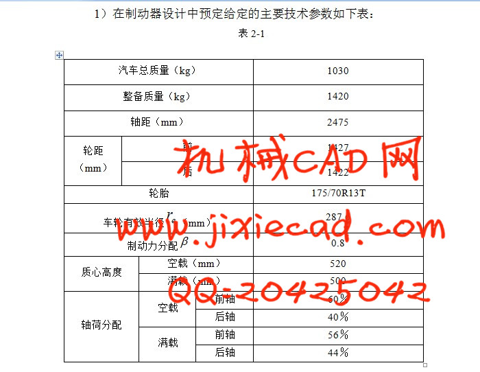
2.1 设计准备 10
2.2制动器的结构方案分析 11
2.2.1各式鼓式制动器优缺点比较 12
2.2.2 制动器类型选择结果 15
2.3 CA7160制动器的结构特点 15
2.4.1 主要参数的确定确定方法 16
2.4.2 CA7160后轮制动器主要参数选择结果 19
2.5 CA7160后轮制动器主要零件的结构设计 19
2.5.1 制动鼓 19
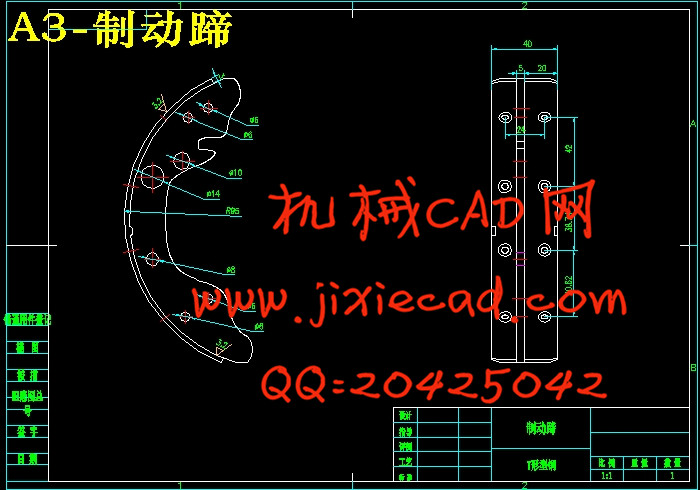
2.5.2 制动蹄 20
2.5.3 制动底板 21
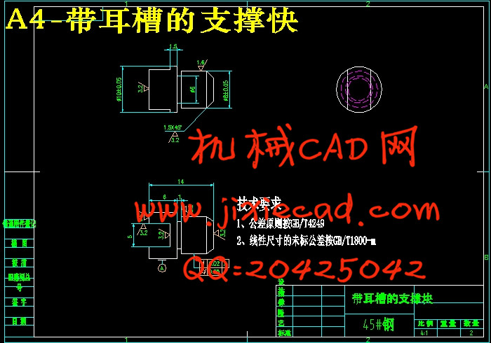
2.5.4 制动蹄的支承 21
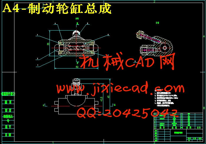
2.5.5 制动轮缸 22
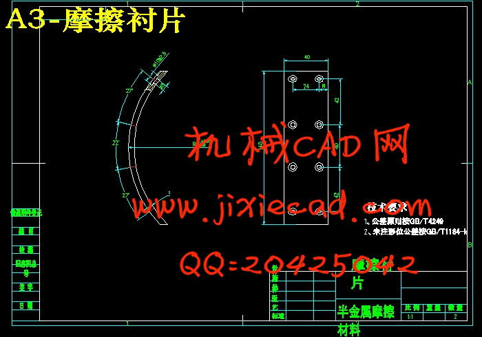
2.5.6 摩擦衬片 22
2.5.7 CA7160后轮制动器主要零件结构设计结果 23
2.5.8 CA7160后轮制动器蹄与鼓之间的间隙自动调整装置 23
2.6 CA7160后轮制动器设计计算 25
2.6.1压力沿衬片的分布规律 25
2.6.2计算蹄片上的制动力矩 26
2.6.3衬片磨损特性的计算 26
2.6.4制动因素分析计算 28
2.6.5制动轮缸直径与工作容积 30
2.7 CA7160后轮制动器零件强度计算 30
2.7.1强度计算准备 30
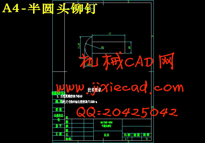
2.7.2紧固摩擦片铆钉得剪应力验算 31
第三章 工艺部分 31
3.1典型零件工艺分析 31
3.1.1毛坯的选择 32
3.1.2 选择定位基准 32
3.1.3 加工工序的安排 33
3.2 总成装配工艺过程 33
3.2.1 编排装配顺序的原则是 33
3.2.2 制动蹄总成装配工艺系统图见图3-3 34
3.2.3 轮缸总成装配工艺系统图见图3-4 34
3.2.4 总成装配工艺系统图见图3-5 34
第四章 设计总结 36
参考文献 37
致 谢 38