设计简介
O型转子式翻车机
摘 要
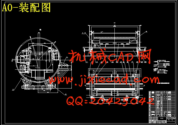
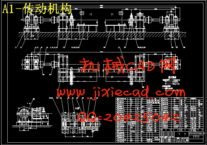
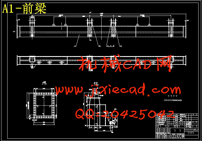
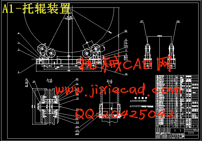
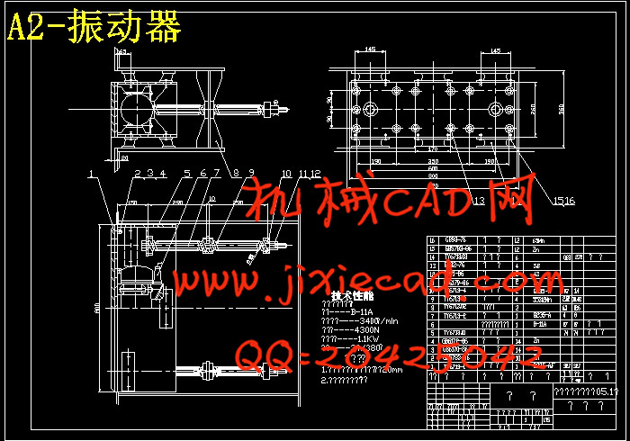
翻车机是一种大型的高效率机械化卸车设备,适用于冶金厂、火力发电厂、烧结厂、化工厂、洗煤厂、水泥厂、港口等大中型企业翻卸铁路敞车所装载的矿石、精矿、煤炭、粮食等散状物料。翻车机按翻卸方式可分为侧倾式和转子式两类。其中转子式翻车机又分为“O”型转子式翻车机和“C”型转子式翻车机两种;转子式翻车机主要由驱动机构、靠压机构、托辊及压紧机构等部分组成。工作原理是将载货敞车推入形似转筒的金属构架内夹紧后,由驱动装置使端环旋转140°~170°,车内的散状物料在自重作用下卸入地下料仓。翻车机的工作状态是由左、右端环同时做旋转运动从而带动整个架体及车厢转动来实现物料的翻卸。其驱动装置是采用双电机驱动,经二级圆柱直齿轮减速器减速,通过联轴器与小齿轮连接,由小齿轮与固定在端环上的大齿轮的啮合带动整体的旋转实现翻车。其靠压机构主要由靠板、液压缸、摇臂组成;而压紧机构主要由压板和液压缸组成。本次设计主要对翻车机的传动方案,左、右端环结构、前、后梁结构、平台、托辊等结构进行了设计;对翻车机的动力学分析及动力学参数进行了计算;对主传动的电机及各主要零部件进行设计并校核;对设备的经济性及环保等各方面也进行了分析。
关键词:转子式翻车机;托辊;靠压机构;驱动装置
O-Rotary Dumper
Abstract
Tipper is a highly efficient large-scale mechanization and Unloading equipment for metallurgical plants, coal-fired power plants, sintering plants, chemical plants, coal washing plant, a cement plant, port and other large and medium-sized enterprises over the railway unloading the gondola car loaded with ore, concentrate , coal, grain and other bulk materials. Tipper unloading by means turn and roll can be divided into two types of rotor. Rotary Car Dumper which is divided into "O"-type rotor-type roll-over and "C"-type rotor two tipper; rotor driven mainly by the tipper body, pressure on agencies, and compacting roller and some other group of institutions into.The working principle is to open freight car laden drum into the shape of the metal framework after clamping, so that by the end of Central Drive Rotation 140 ° ~ 170 °, the bulk material inside the vehicle under the self-dumping hopper into the ground. Tipper is the work of the state of the left and the right end of the ring rotation at the same time to do so bring the whole body and the inside rotation planes to achieve over the dumping of materials. The driver device is a dual-motor drive, the two speed gear reducer cylindrical straight through coupling with the small gear connected with the small gear ring fixed in the side of the meshing gear drive to achieve the rotation of the overall roll-over. By the pressure of its body mainly by the on board, hydraulic cylinders, rocker components; and pressed mainly by the plate and hydraulic cylinder components. The design of the main drive of the roll-over machine program, the left and the right end of the ring structure, the former, Later Liang structure, platforms, roller structure design, etc.; the dynamics of the tipper and kinetic parameters were calculated; on the main drive The main components of the motor and the design and verification; the economy of equipment and environmental protection are also analyzed.
Key words: rotor-type roll-over machine; idler; pressure on institutions; drive
目 录
1 绪论 1
1.1 课题的选择 1
1.2 翻车机的类型及原理 1
1.2.1 转子式翻车机 2
1.2.2 侧卸式翻车机 4
1.3 翻车机设计的内容 6
2 设计方案的选择及评定 7
2.1 传动方案的设计 7
2.2 设计方案的评定 7
2.3 设计参数 8
3 传动装置的设计 9
3.1 选择电动机 9
3.1.1驱动功率计算 9
3.1.2选择电机的型号 13
3.2传动装置传动比的分配 14
4 主要零件的设计和校核 16
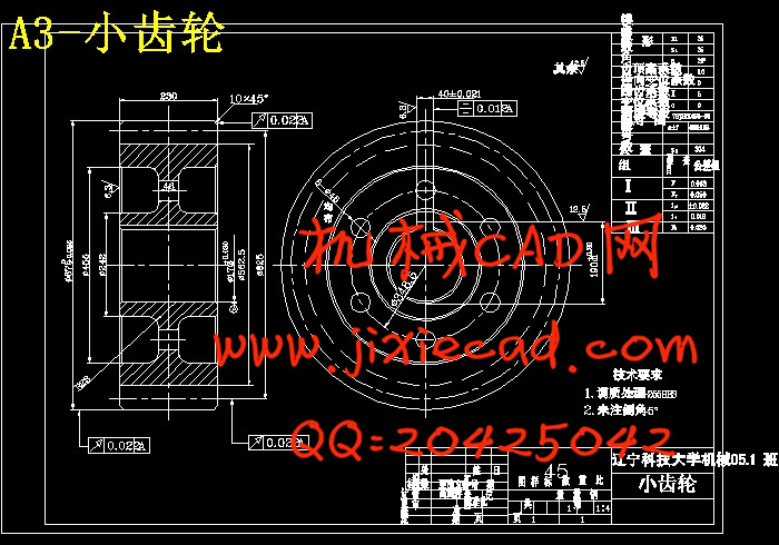
4.1齿轮的设计计算 16
4.1.1 选定齿轮类型、精度等级、材料及齿数 16
4.1.2 按齿面接触强度设计 16
4.1.3 按齿根弯曲强度设计 19
4.1.4 齿轮几何尺寸计算 20
4.2液压缸的设计 21
4.2.1 液压缸的选用 21
4.2.2 液压缸的校核 22
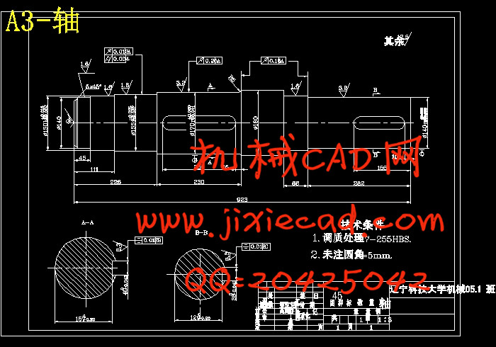
4.3 轴的设计 23
4.3.1 轴的结构设计 23
4.3.2 轴的计算 25
4.4轴承的选择和校核 28
4.4.1 轴承的选择 28
4.4.2 轴承寿命的验算 29
4.5键的强度校核 30
5 联轴器的选择 31
6托辊与端环之间接触强度校核 32
7 润滑与密封 34
8 经济性分析 35
8.1传动方案经济性分析 35
8.2 结构经济性分析 35
8.3 环保经济性分析 36
结束语 37
致谢 38
参考文献 39
摘 要
翻车机是一种大型的高效率机械化卸车设备,适用于冶金厂、火力发电厂、烧结厂、化工厂、洗煤厂、水泥厂、港口等大中型企业翻卸铁路敞车所装载的矿石、精矿、煤炭、粮食等散状物料。翻车机按翻卸方式可分为侧倾式和转子式两类。其中转子式翻车机又分为“O”型转子式翻车机和“C”型转子式翻车机两种;转子式翻车机主要由驱动机构、靠压机构、托辊及压紧机构等部分组成。工作原理是将载货敞车推入形似转筒的金属构架内夹紧后,由驱动装置使端环旋转140°~170°,车内的散状物料在自重作用下卸入地下料仓。翻车机的工作状态是由左、右端环同时做旋转运动从而带动整个架体及车厢转动来实现物料的翻卸。其驱动装置是采用双电机驱动,经二级圆柱直齿轮减速器减速,通过联轴器与小齿轮连接,由小齿轮与固定在端环上的大齿轮的啮合带动整体的旋转实现翻车。其靠压机构主要由靠板、液压缸、摇臂组成;而压紧机构主要由压板和液压缸组成。本次设计主要对翻车机的传动方案,左、右端环结构、前、后梁结构、平台、托辊等结构进行了设计;对翻车机的动力学分析及动力学参数进行了计算;对主传动的电机及各主要零部件进行设计并校核;对设备的经济性及环保等各方面也进行了分析。
关键词:转子式翻车机;托辊;靠压机构;驱动装置
O-Rotary Dumper
Abstract
Tipper is a highly efficient large-scale mechanization and Unloading equipment for metallurgical plants, coal-fired power plants, sintering plants, chemical plants, coal washing plant, a cement plant, port and other large and medium-sized enterprises over the railway unloading the gondola car loaded with ore, concentrate , coal, grain and other bulk materials. Tipper unloading by means turn and roll can be divided into two types of rotor. Rotary Car Dumper which is divided into "O"-type rotor-type roll-over and "C"-type rotor two tipper; rotor driven mainly by the tipper body, pressure on agencies, and compacting roller and some other group of institutions into.The working principle is to open freight car laden drum into the shape of the metal framework after clamping, so that by the end of Central Drive Rotation 140 ° ~ 170 °, the bulk material inside the vehicle under the self-dumping hopper into the ground. Tipper is the work of the state of the left and the right end of the ring rotation at the same time to do so bring the whole body and the inside rotation planes to achieve over the dumping of materials. The driver device is a dual-motor drive, the two speed gear reducer cylindrical straight through coupling with the small gear connected with the small gear ring fixed in the side of the meshing gear drive to achieve the rotation of the overall roll-over. By the pressure of its body mainly by the on board, hydraulic cylinders, rocker components; and pressed mainly by the plate and hydraulic cylinder components. The design of the main drive of the roll-over machine program, the left and the right end of the ring structure, the former, Later Liang structure, platforms, roller structure design, etc.; the dynamics of the tipper and kinetic parameters were calculated; on the main drive The main components of the motor and the design and verification; the economy of equipment and environmental protection are also analyzed.
Key words: rotor-type roll-over machine; idler; pressure on institutions; drive
目 录
1 绪论 1
1.1 课题的选择 1
1.2 翻车机的类型及原理 1
1.2.1 转子式翻车机 2
1.2.2 侧卸式翻车机 4
1.3 翻车机设计的内容 6
2 设计方案的选择及评定 7
2.1 传动方案的设计 7
2.2 设计方案的评定 7
2.3 设计参数 8
3 传动装置的设计 9
3.1 选择电动机 9
3.1.1驱动功率计算 9
3.1.2选择电机的型号 13
3.2传动装置传动比的分配 14
4 主要零件的设计和校核 16
4.1齿轮的设计计算 16
4.1.1 选定齿轮类型、精度等级、材料及齿数 16
4.1.2 按齿面接触强度设计 16
4.1.3 按齿根弯曲强度设计 19
4.1.4 齿轮几何尺寸计算 20
4.2液压缸的设计 21
4.2.1 液压缸的选用 21
4.2.2 液压缸的校核 22
4.3 轴的设计 23
4.3.1 轴的结构设计 23
4.3.2 轴的计算 25
4.4轴承的选择和校核 28
4.4.1 轴承的选择 28
4.4.2 轴承寿命的验算 29
4.5键的强度校核 30
5 联轴器的选择 31
6托辊与端环之间接触强度校核 32
7 润滑与密封 34
8 经济性分析 35
8.1传动方案经济性分析 35
8.2 结构经济性分析 35
8.3 环保经济性分析 36
结束语 37
致谢 38
参考文献 39