设计简介
摘要
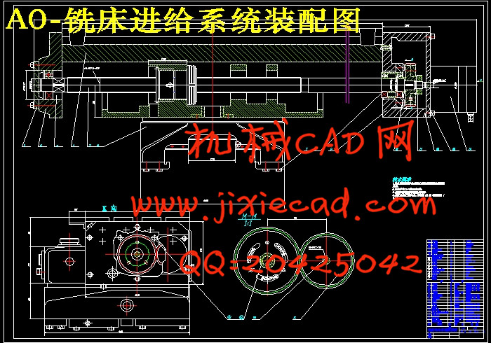
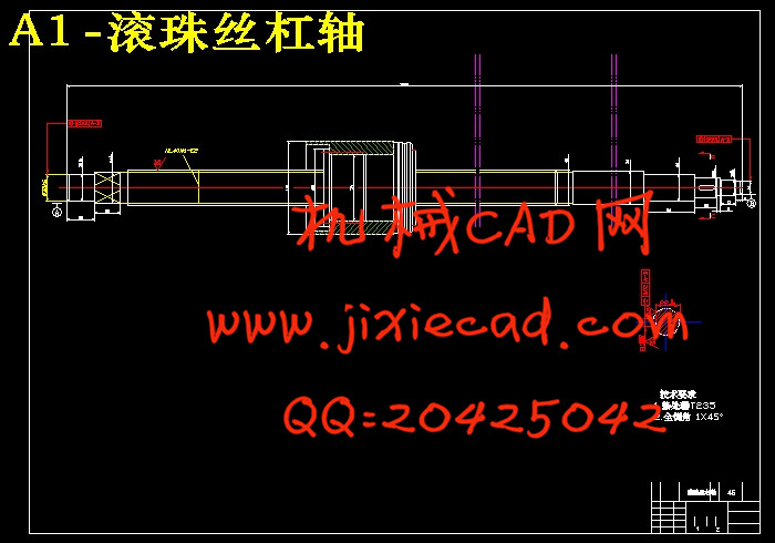
本文主要研究了X502经济型中档精度数控铣床的纵向进给机构的设计及其改造。本文对数控铣床纵向进给系统的设计与改造方案进行了重点论述,对该机构的主要组成部件:滚珠丝杠副、交流伺服电机、联轴器等进行了设计计算与选型。其中对滚珠丝杠副、交流伺服电机的设计计算及选型作了详细论述。进行这一设计主要是为了进一步地提高数控铣床纵向进给机构的定位精度,重复定位精度以及改造手动进给装置,以使其能够可靠地运行,且能满足各项性能指标的要求,达到预期的结果,即满足设计任务书的要求。最后, 本文还对各个零部件进行了设计,并绘制该数控铣床纵向进给机构和工作台与滑台的装配图。此结构简单可靠,可应用于相似的各类数控铣床上。
关键词: 数控车床; 纵向进给; 设计; 改造
ABSTRACT
This article mainly told the research, the designing and transformation on the longitudinal motion system and track lubrication mechanism of CA6140 economic medium precision NC machine. The article made a brilliant exposition on the designing and transformation scheme of the longitudinal motion system and track lubrication mechanism of NC machine. The article also exposed brilliantly the mechanism’s mail parts: the ball-race bearing, the servo-electric machine, the coupling and so on. Doing the design is for the sake of improving the site precision, duplicate site precision and transformating the Longitudinal motion system .So it can work credibility, meet the request of every property norm, come to the expected consequence, and fulfill the require of design assignment list. Besides, the author has designed and drawed all of mechanism’ parts, and also drawed the assemble chart. This mechanism is simple and reliable, it can apply to every similar NC machine.
Key words: NC machine;longitudinal motion;design
目 录
第一章 绪论
1.1数控铣床简介………………………………………………………...1
1.2数控铣床的组成……………………………………………………...1
1.3数控铣床的分类………………………………………………….…..2
1.4数控铣床的用途和工艺特点…………………………………….…..2
1.5我国数控产业的现状………………………………………………...3
1.6数控产业发展面临的问题……………………………………...……4
1.7发展趋势………………………………………………………….…..4
1.8济型数控铣床改造的条件...................................................................5
第二章 数控铣床进给传动装置设计
2.1伺服系统的基本设计要求……………………………………...……5
2.2伺服系统机械传动结构设计特点…………………...………………5
2.3纵向伺服进给系统设计的基本要求…………………...……………6
2.4伺服系统对伺服电机的要求…………………………………...……6
第三章 总体设计方案论证……………………….………………….7
3.1数控系统的选择……………………………………………………...8
3.2驱动元件选择.......................................................................................9
3.3传动机构选择………………………………………………………...9
3.4联轴器选择…………………………………….……………………10
3.5导轨副选择…………………………………………….……………11
3.6总体设计方案的确………………………………………………….11
3.6.1纵向进给系统的改造……………………………………………..12
第四章 纵向进给机构的设计与计算………………………………12
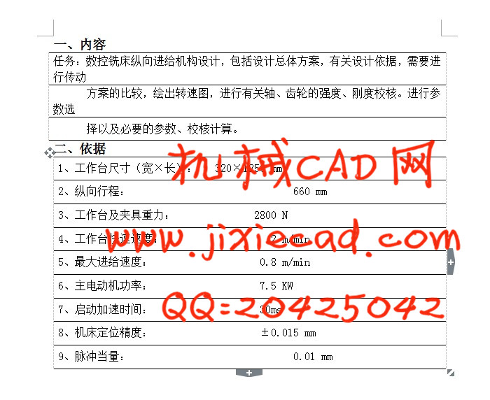
4.1已知参数条件……………………………………………………….12
4.2滚珠丝杆副主要参数的确定………………………..…...…………13
4.3设计步骤…………………………………………………..………...13
4.4设计计算………………………………………………….…………14
4.5滚珠丝杠选择.....................................................................................15
4.5.1滚珠丝杠精度………………………………………….………….15
4.5.2滚珠丝杠选择..................................................................................15
4.6滚珠丝杠支承选择.............................................................................17
4.7滚珠丝杠螺母副间隙消除和预紧.....................................................20
4.8选择伺服电机.....................................................................................21
4.8.1最大的切削负载转矩计算..............................................................21
4.8.2负载惯量计算..................................................................................22
4.8.3空载加速转矩计算..........................................................................23
4.9伺服系统增益.....................................................................................24
4.10精度验算...........................................................................................24
4.10.1伺服刚度........................................................................................26
4.10.2滚珠丝杠的拉压刚度....................................................................26
4.10.3丝杠轴承的轴向刚度....................................................................26
4.10.4滚珠丝杠螺母的接触刚度............................................................26
4.10.5挠性联轴节扭转刚度....................................................................26
4.10.6综合刚度........................................................................................27
4.10.7弹性变形........................................................................................27
4.10.8定位误差验算................................................................................27
第五章FANUC数控零件编程
5.1数控铣床的对刀操作.........................................................................28
5.1.1 G92设定工件坐标系对刀
5.1.2 G54~G59设定工件坐标系对刀
5.2零件加工实例
小结…………………………………………………………………….
参考文献………………………………………………………………..
致谢……………………………………………………………………..
附件清单………………………………………………………………..
本文主要研究了X502经济型中档精度数控铣床的纵向进给机构的设计及其改造。本文对数控铣床纵向进给系统的设计与改造方案进行了重点论述,对该机构的主要组成部件:滚珠丝杠副、交流伺服电机、联轴器等进行了设计计算与选型。其中对滚珠丝杠副、交流伺服电机的设计计算及选型作了详细论述。进行这一设计主要是为了进一步地提高数控铣床纵向进给机构的定位精度,重复定位精度以及改造手动进给装置,以使其能够可靠地运行,且能满足各项性能指标的要求,达到预期的结果,即满足设计任务书的要求。最后, 本文还对各个零部件进行了设计,并绘制该数控铣床纵向进给机构和工作台与滑台的装配图。此结构简单可靠,可应用于相似的各类数控铣床上。
关键词: 数控车床; 纵向进给; 设计; 改造
ABSTRACT
This article mainly told the research, the designing and transformation on the longitudinal motion system and track lubrication mechanism of CA6140 economic medium precision NC machine. The article made a brilliant exposition on the designing and transformation scheme of the longitudinal motion system and track lubrication mechanism of NC machine. The article also exposed brilliantly the mechanism’s mail parts: the ball-race bearing, the servo-electric machine, the coupling and so on. Doing the design is for the sake of improving the site precision, duplicate site precision and transformating the Longitudinal motion system .So it can work credibility, meet the request of every property norm, come to the expected consequence, and fulfill the require of design assignment list. Besides, the author has designed and drawed all of mechanism’ parts, and also drawed the assemble chart. This mechanism is simple and reliable, it can apply to every similar NC machine.
Key words: NC machine;longitudinal motion;design
目 录
第一章 绪论
1.1数控铣床简介………………………………………………………...1
1.2数控铣床的组成……………………………………………………...1
1.3数控铣床的分类………………………………………………….…..2
1.4数控铣床的用途和工艺特点…………………………………….…..2
1.5我国数控产业的现状………………………………………………...3
1.6数控产业发展面临的问题……………………………………...……4
1.7发展趋势………………………………………………………….…..4
1.8济型数控铣床改造的条件...................................................................5
第二章 数控铣床进给传动装置设计
2.1伺服系统的基本设计要求……………………………………...……5
2.2伺服系统机械传动结构设计特点…………………...………………5
2.3纵向伺服进给系统设计的基本要求…………………...……………6
2.4伺服系统对伺服电机的要求…………………………………...……6
第三章 总体设计方案论证……………………….………………….7
3.1数控系统的选择……………………………………………………...8
3.2驱动元件选择.......................................................................................9
3.3传动机构选择………………………………………………………...9
3.4联轴器选择…………………………………….……………………10
3.5导轨副选择…………………………………………….……………11
3.6总体设计方案的确………………………………………………….11
3.6.1纵向进给系统的改造……………………………………………..12
第四章 纵向进给机构的设计与计算………………………………12
4.1已知参数条件……………………………………………………….12
4.2滚珠丝杆副主要参数的确定………………………..…...…………13
4.3设计步骤…………………………………………………..………...13
4.4设计计算………………………………………………….…………14
4.5滚珠丝杠选择.....................................................................................15
4.5.1滚珠丝杠精度………………………………………….………….15
4.5.2滚珠丝杠选择..................................................................................15
4.6滚珠丝杠支承选择.............................................................................17
4.7滚珠丝杠螺母副间隙消除和预紧.....................................................20
4.8选择伺服电机.....................................................................................21
4.8.1最大的切削负载转矩计算..............................................................21
4.8.2负载惯量计算..................................................................................22
4.8.3空载加速转矩计算..........................................................................23
4.9伺服系统增益.....................................................................................24
4.10精度验算...........................................................................................24
4.10.1伺服刚度........................................................................................26
4.10.2滚珠丝杠的拉压刚度....................................................................26
4.10.3丝杠轴承的轴向刚度....................................................................26
4.10.4滚珠丝杠螺母的接触刚度............................................................26
4.10.5挠性联轴节扭转刚度....................................................................26
4.10.6综合刚度........................................................................................27
4.10.7弹性变形........................................................................................27
4.10.8定位误差验算................................................................................27
第五章FANUC数控零件编程
5.1数控铣床的对刀操作.........................................................................28
5.1.1 G92设定工件坐标系对刀
5.1.2 G54~G59设定工件坐标系对刀
5.2零件加工实例
小结…………………………………………………………………….
参考文献………………………………………………………………..
致谢……………………………………………………………………..
附件清单………………………………………………………………..