设计简介
摘 要
从汽车诞生时起,车辆制动系统在车辆的安全方面就起着决定性作用。据有关资料的介绍,在由于车辆本身的问题而造成的交通事故中,制动系统故障引起的事故为总数的45%。可见,制动器是保证行车安全的极为重要的一个系统。此外,制动器的好坏直接影响车辆的平均车速和车辆的运输效率,也就是保证运输经济效益的重要因素。制动器是汽车制动系统中最重要的安全部件,对汽车制动器进行深入的分析具有十分重要的意义。
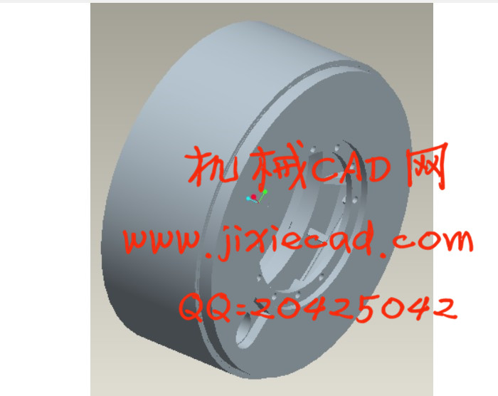
本设计说明书主要介绍了鼓式制动器的设计。首先介绍了鼓式制动器的发展及其结构,并通过对鼓式制动器和盘式制动器的结构及优缺点进行分析。最终确定采用领从蹄式鼓式制动器。在计算出设计参数后,通过PRO/E三维制图软件建立模型,用ANSYS软件进行对制动器零件的校核分析。
关键词:制动鼓;摩擦片;制动蹄;安全性;气压制动
ABSTRACT
Born from the car, the vehicle braking system on the vehicle's security plays a decisive role. According to relevant information,the vehicle cause problems of the traffic accident ,while the brake system failure is the total of 45% of the accident. Thus, the brake is to ensure the safety of the most important about a system.In addition, the brake is a direct impact on the average speed and efficiency of transport, ensure the efficiency of transport is an important factor. the brake is the brake system the most important of security parts, while the brake on the analysis is therefore tremendously significant.
The main specification of the design introduced in order to study Santana2000 car in order to carry out the design of drum brake. First introduced the development of brake drum and its structure, and through the drum brake and disc brake structure and analysis of advantages and disadvantages. Ultimately determine the use of lead from the hoof-style drum brakes. In the calculation of design parameters, through the PRO / E model of three-dimensional graphics software, using ANSYS software to check on the analysis of the brake parts
Key words: Brake;Parking brake;Drum brake;Disc brakes;Pressure brake
目 录
摘要………………………………………………………………………………………Ⅰ
Abstract …………………………………………………………………………………Ⅱ
第1章 绪论………………………………………………………………………………1
1.1课题背景及目的……………………………………………………………………1
1.2国内外研究现状................................………………………………………………3
1.3课题研究方法……………........................…………………………………………4
1.3预期目标................................………………………………………………………4
1.4设计主要内容…....................................……………………………………………4
第2章 总体设计方案…………………………………………………………………5
2.1制动原理与工作过程………………................................…………………………6
2.2制动器的结构方案分析…..…………………..........................……………………7
2.3鼓式制动器……………………………….........................................…………...…7
2.4方案确定………………………………............................................…………..…10
2.5本章小结…………………………………………………………………..………10
第3章 制动器的设计计算…………………………………………………………11
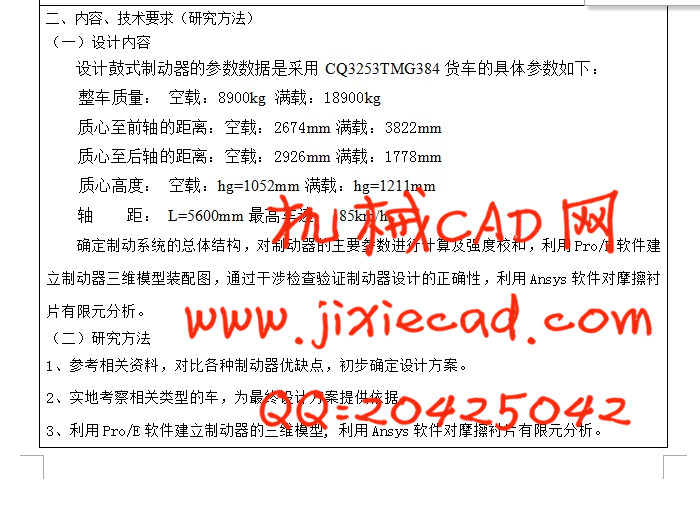
3.1基本参数………………………………..……………............……………………11
3.2同步附着系数的确定…………………..………………....................……………11
3.3制动器最大制动力矩的确定….….....................................………………………13
3.4鼓式制动器的主要参数选择……………………………………..………………14
3.4.1制动鼓直径….....................…...…………………...………………………15
3.4.2摩擦片的宽度和包角...……..…………………………..…………………15
3.4.3制动器中心到张开力之间的作用…..………………………..…..……….16
3.4.4制动蹄支承销中心位置…..………………………..…..................……….17
3.4.5摩擦片摩擦系数……….........……..……………........……………………17
3.4.6制动底板的材料选择...……..……………………………………..………18
3.4.7制动气室的选择………………………………………........………...……18
3.5同一制动器各蹄产生的制动力矩.........................………………………………19
3.6制动器制动因数的计算..........................................………………………………21
3.7本章小结……………………………………..........................................................22
第4章 制动性能分析…………………………………………………………………23
4.1制动性能评价………………..………………………………………................…23
4.2制动效能……………………………………........……………..…………………23
4.3制动效能的恒定性……………………………….....………….…………………23
4.4制动时汽车的方向稳定性性………………………………….………………….23
4.5制动器动力分配曲线…………………………….……………….....................…24
4.6制动减速度………………………………….……………….............................…24
4.7制动距离………………………………….……………….................................…25
4.8摩擦衬片的磨损特性…………………………………….…….…………………25
4.9驻车制动计算…………………………………………..............…………………27
4.10本章小结………………..…………………………………..……………………28
第5章 鼓式制动器的三维建模……………………………………………………29
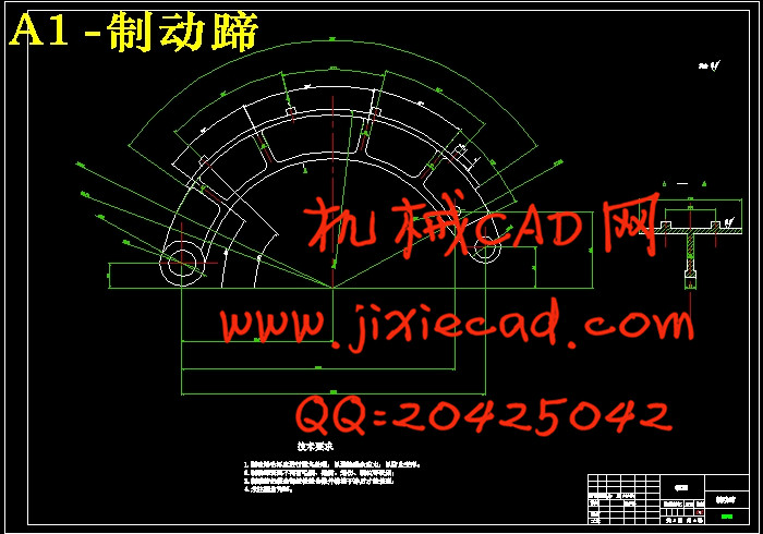
5.1制动蹄的建模………………………………………………………………29
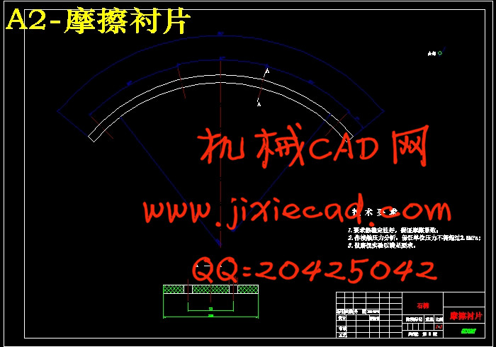
5.2摩擦片的建模………………………………..…………………………30
5.3弹簧的建模…………………………………………………..……………31
5.4凸轮轴的建模…………………………..………………………………………32
5.5制动底板的建模…………………………..………………………………………32
5.6制动鼓的建模…………………………..………………………………………32
5.7其他零件的建模…………………………..………………………………………34
5.8鼓式制动器的装配…………………………..……………………………………35
5.9鼓式制动器的分解………………………..………………………………………35
5.10本章小结…………………………..………………………………………36
第6章 制动器零件的有限元分析…………………………………………………37
6.1静力分析…………………………………………………..................……………37
6.1.1摩擦片的分析….....................…...………………...………………………37
6.1.2制动蹄的分析...……..………………………............…..…………………41
6.1.3制动鼓的分析…..………………………..…..……….................................44
6.2动力分析………………………………..……........................……………………46
6.3本章小结…………………………………………………..……................………48
结论………………………………………………………………………………………49
参考文献 ………………………………………………………………………………50
致谢………………………………………………………………………………………51
从汽车诞生时起,车辆制动系统在车辆的安全方面就起着决定性作用。据有关资料的介绍,在由于车辆本身的问题而造成的交通事故中,制动系统故障引起的事故为总数的45%。可见,制动器是保证行车安全的极为重要的一个系统。此外,制动器的好坏直接影响车辆的平均车速和车辆的运输效率,也就是保证运输经济效益的重要因素。制动器是汽车制动系统中最重要的安全部件,对汽车制动器进行深入的分析具有十分重要的意义。
本设计说明书主要介绍了鼓式制动器的设计。首先介绍了鼓式制动器的发展及其结构,并通过对鼓式制动器和盘式制动器的结构及优缺点进行分析。最终确定采用领从蹄式鼓式制动器。在计算出设计参数后,通过PRO/E三维制图软件建立模型,用ANSYS软件进行对制动器零件的校核分析。
关键词:制动鼓;摩擦片;制动蹄;安全性;气压制动
ABSTRACT
Born from the car, the vehicle braking system on the vehicle's security plays a decisive role. According to relevant information,the vehicle cause problems of the traffic accident ,while the brake system failure is the total of 45% of the accident. Thus, the brake is to ensure the safety of the most important about a system.In addition, the brake is a direct impact on the average speed and efficiency of transport, ensure the efficiency of transport is an important factor. the brake is the brake system the most important of security parts, while the brake on the analysis is therefore tremendously significant.
The main specification of the design introduced in order to study Santana2000 car in order to carry out the design of drum brake. First introduced the development of brake drum and its structure, and through the drum brake and disc brake structure and analysis of advantages and disadvantages. Ultimately determine the use of lead from the hoof-style drum brakes. In the calculation of design parameters, through the PRO / E model of three-dimensional graphics software, using ANSYS software to check on the analysis of the brake parts
Key words: Brake;Parking brake;Drum brake;Disc brakes;Pressure brake
目 录
摘要………………………………………………………………………………………Ⅰ
Abstract …………………………………………………………………………………Ⅱ
第1章 绪论………………………………………………………………………………1
1.1课题背景及目的……………………………………………………………………1
1.2国内外研究现状................................………………………………………………3
1.3课题研究方法……………........................…………………………………………4
1.3预期目标................................………………………………………………………4
1.4设计主要内容…....................................……………………………………………4
第2章 总体设计方案…………………………………………………………………5
2.1制动原理与工作过程………………................................…………………………6
2.2制动器的结构方案分析…..…………………..........................……………………7
2.3鼓式制动器……………………………….........................................…………...…7
2.4方案确定………………………………............................................…………..…10
2.5本章小结…………………………………………………………………..………10
第3章 制动器的设计计算…………………………………………………………11
3.1基本参数………………………………..……………............……………………11
3.2同步附着系数的确定…………………..………………....................……………11
3.3制动器最大制动力矩的确定….….....................................………………………13
3.4鼓式制动器的主要参数选择……………………………………..………………14
3.4.1制动鼓直径….....................…...…………………...………………………15
3.4.2摩擦片的宽度和包角...……..…………………………..…………………15
3.4.3制动器中心到张开力之间的作用…..………………………..…..……….16
3.4.4制动蹄支承销中心位置…..………………………..…..................……….17
3.4.5摩擦片摩擦系数……….........……..……………........……………………17
3.4.6制动底板的材料选择...……..……………………………………..………18
3.4.7制动气室的选择………………………………………........………...……18
3.5同一制动器各蹄产生的制动力矩.........................………………………………19
3.6制动器制动因数的计算..........................................………………………………21
3.7本章小结……………………………………..........................................................22
第4章 制动性能分析…………………………………………………………………23
4.1制动性能评价………………..………………………………………................…23
4.2制动效能……………………………………........……………..…………………23
4.3制动效能的恒定性……………………………….....………….…………………23
4.4制动时汽车的方向稳定性性………………………………….………………….23
4.5制动器动力分配曲线…………………………….……………….....................…24
4.6制动减速度………………………………….……………….............................…24
4.7制动距离………………………………….……………….................................…25
4.8摩擦衬片的磨损特性…………………………………….…….…………………25
4.9驻车制动计算…………………………………………..............…………………27
4.10本章小结………………..…………………………………..……………………28
第5章 鼓式制动器的三维建模……………………………………………………29
5.1制动蹄的建模………………………………………………………………29
5.2摩擦片的建模………………………………..…………………………30
5.3弹簧的建模…………………………………………………..……………31
5.4凸轮轴的建模…………………………..………………………………………32
5.5制动底板的建模…………………………..………………………………………32
5.6制动鼓的建模…………………………..………………………………………32
5.7其他零件的建模…………………………..………………………………………34
5.8鼓式制动器的装配…………………………..……………………………………35
5.9鼓式制动器的分解………………………..………………………………………35
5.10本章小结…………………………..………………………………………36
第6章 制动器零件的有限元分析…………………………………………………37
6.1静力分析…………………………………………………..................……………37
6.1.1摩擦片的分析….....................…...………………...………………………37
6.1.2制动蹄的分析...……..………………………............…..…………………41
6.1.3制动鼓的分析…..………………………..…..……….................................44
6.2动力分析………………………………..……........................……………………46
6.3本章小结…………………………………………………..……................………48
结论………………………………………………………………………………………49
参考文献 ………………………………………………………………………………50
致谢………………………………………………………………………………………51