设计简介
摘 要
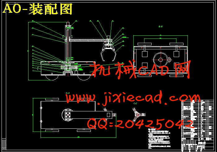
很多地方是我们人类没法进去的,因为其中的一些东西已经对我们造成了生命的威胁,但我们又有必须进去的理由。在这种场合下,机械就能为我们解决这些问题,因为它可以代替我们进行一些危险操作,用来取代人力来工作。我们设计的抓物机器车是在机械化,自动化生产过程中发展起来的一种将机械手和搬运车联系为一体的产品。使其能抓物运动,可以在地形复杂或恶劣、危险的环境里替人完成物体的搬运或者障碍的清除等工作。
抓物机器车的设计主要是通过无线通信来控制小车的前进、后退或者转弯,并由螺杆转动,带动螺杆上的螺母上下移动,再通过连杆结构实现抓爪的闭合,从而实现抓物动作。丝杆竖直放置,转臂固定在丝杆螺母上,步进电机带动丝杆旋转,螺母会上下移动,转臂也会上下移动,也就是机械手上下移动,满足了机械手降下抓物,升高移动物体的情况。机械手的转动,在由齿轮带动固定丝杆的中间件转动而实现的。
关键词:机器车;抓物;丝杆
Abstract
Many things that we humans can not go , because some of these things have been a threat to our life , but the reason we have to go in there . In this case , our machinery will be able to solve these problems. Because it can replace us doing some dangerous operation , to replace manpower to work. Because it can replace us some dangerous operation, to replace manpower to work. We have designed the Grasping machine car that developed in the mechanization and automation of the production process and the robot van combined into one product. So that it can catch things exercise can help people complete the removal of an object or obstacle clearance work in complex terrain or harsh, dangerous environment.
Grasping machine car designed primarily controlled by a wireless communication car forward, backward, or turn. by the screw rotates, driven to move up and down the screw on the nut, and then realize gripper closure through the link structure to realize grasping objects actions . Screw placed vertically, and the arm is fixed on screw nut, stepper motor driven rotary screw, nut meeting next move, the arm will move up and down, which is under the robot moves down to meet the robot grasping objects, elevated movement of the object. Turn the robot, driven by fixed-gear screw rotation middleware
implementation.
Key words: machine car; grasping objects; screw
1 设计方案 2
1.1 设计内容 2
1.2 设计目的 2
1.3 方案的选择 2
2 机械手的设计 3
2.1 抓手结构的设计 3
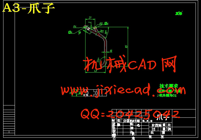
2.2 爪片的设计 5
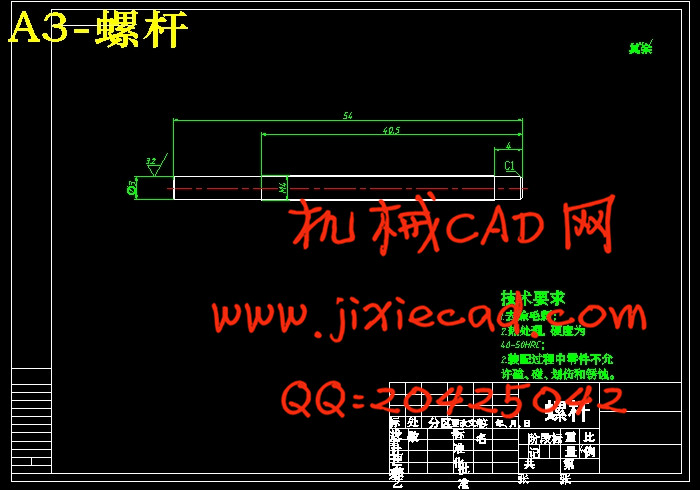
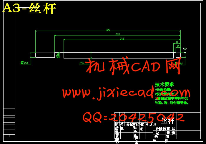
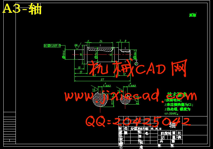
2.3 螺杆的设计 7
2.3.1确定螺纹中径 8
2.3.2螺杆的强度计算 9
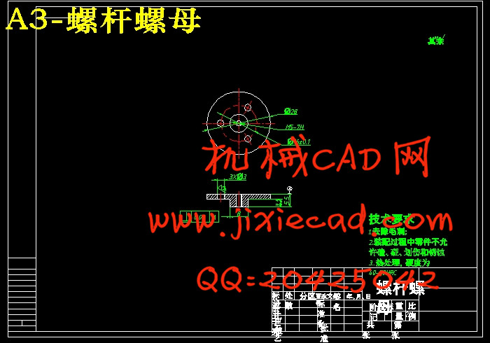
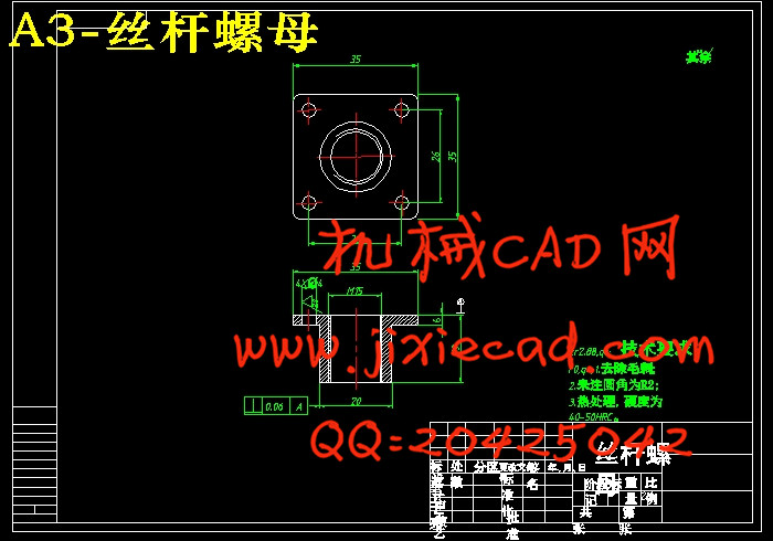
2.3.3螺母螺纹牙的强度计算 9
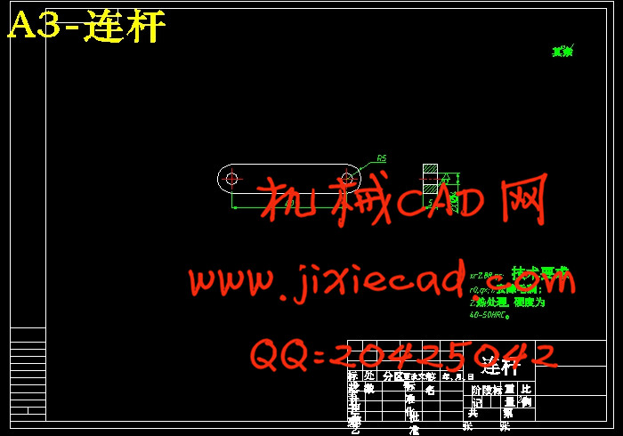
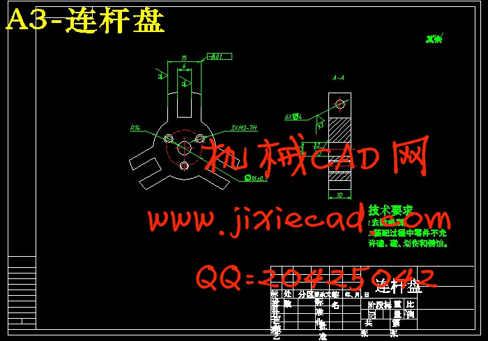
2.4 连杆盘的设计 10
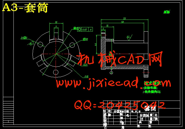
2.5 套筒的设计 11
2.5.1套筒的尺寸 11
2.5.2螺栓的选择 11
2.5.3螺纹连接的防松 13
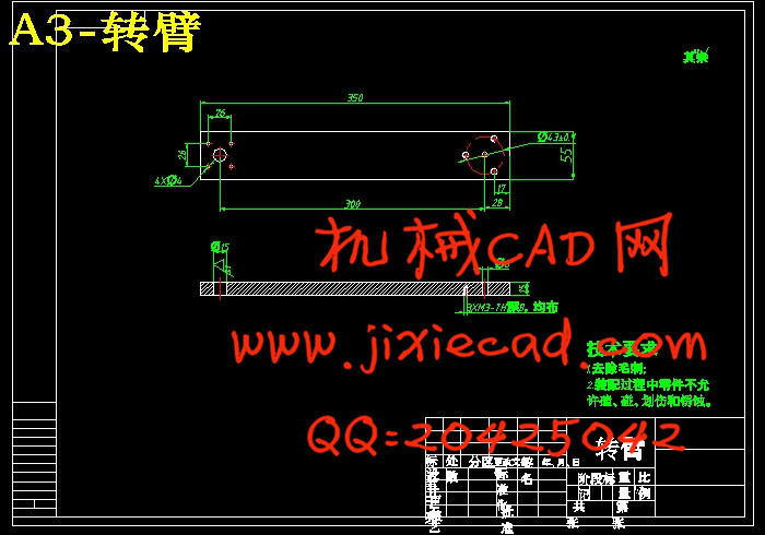
3 转臂的设计 13
3.1 受力分析 13
3.2 转臂的尺寸计算 14
3.3 螺栓的设计 15
3.3.1螺栓组结构设计 15
3.3.2螺栓受力分析 15
4 滑动丝杆的设计 16
4.1 螺纹牙型的选择 16
4.2 螺距选择 16
4.3 丝杆直径的确定 16
4.4 螺杆的强度计算 17
4.5 螺母螺纹牙的强度计算 17
4.6 丝杆的长度 18
4.7 丝杆螺母的传动形式 18
4.8 丝杆的固定 19
4.9 轴承的选择 19
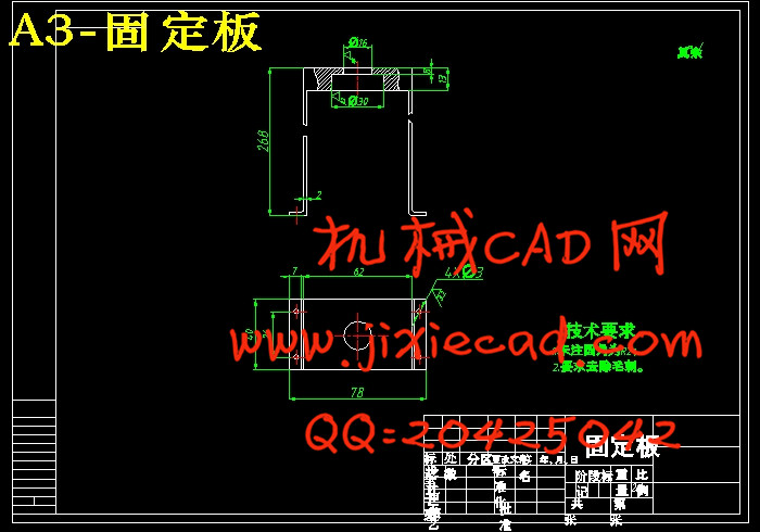
4.10 固定板的设计 21
4.10.1固定板的结构 22
4.10.2固定架的固定 22
5 转盘的设计 23
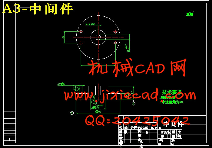
5.1 中间板的设计 23
5.2 键的选择 25
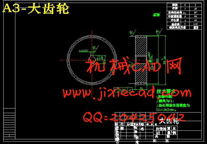
5.3 齿轮的设计 25
5.3.1选定齿轮类型,精度等级,材料及模数 25
5.3.2按齿面接触疲劳强度设计 26
5.3.3按齿根弯曲疲劳强度设计 27
5.3.4几何尺寸计算 27
5.4 轴的设计 28
6 车身的设计 30
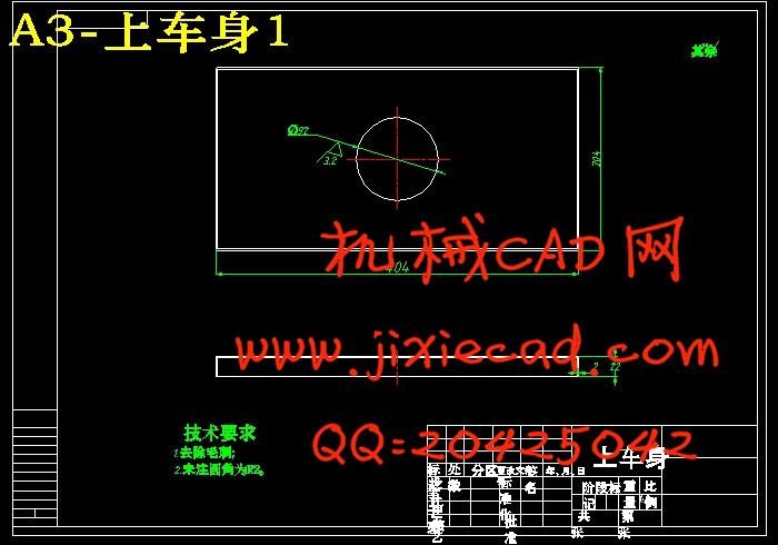
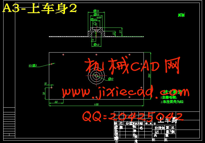
6.1 上车身的设计 30
6.2 下车身的设计 31
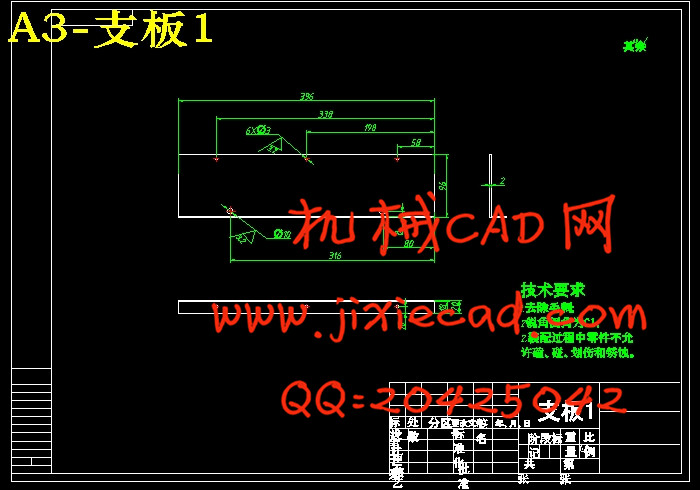
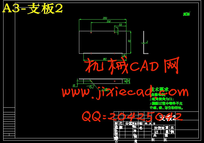
6.3 支板的设计 35
6.3.1支板的结构 35
6.3.2尺寸计算 35
6.3.3支板的连接 36
6.3.4轮子孔的设计 36
7 solidworks的建模和仿真 37
8 总结 38
谢 辞 39
参考文献 40
很多地方是我们人类没法进去的,因为其中的一些东西已经对我们造成了生命的威胁,但我们又有必须进去的理由。在这种场合下,机械就能为我们解决这些问题,因为它可以代替我们进行一些危险操作,用来取代人力来工作。我们设计的抓物机器车是在机械化,自动化生产过程中发展起来的一种将机械手和搬运车联系为一体的产品。使其能抓物运动,可以在地形复杂或恶劣、危险的环境里替人完成物体的搬运或者障碍的清除等工作。
抓物机器车的设计主要是通过无线通信来控制小车的前进、后退或者转弯,并由螺杆转动,带动螺杆上的螺母上下移动,再通过连杆结构实现抓爪的闭合,从而实现抓物动作。丝杆竖直放置,转臂固定在丝杆螺母上,步进电机带动丝杆旋转,螺母会上下移动,转臂也会上下移动,也就是机械手上下移动,满足了机械手降下抓物,升高移动物体的情况。机械手的转动,在由齿轮带动固定丝杆的中间件转动而实现的。
关键词:机器车;抓物;丝杆
Abstract
Many things that we humans can not go , because some of these things have been a threat to our life , but the reason we have to go in there . In this case , our machinery will be able to solve these problems. Because it can replace us doing some dangerous operation , to replace manpower to work. Because it can replace us some dangerous operation, to replace manpower to work. We have designed the Grasping machine car that developed in the mechanization and automation of the production process and the robot van combined into one product. So that it can catch things exercise can help people complete the removal of an object or obstacle clearance work in complex terrain or harsh, dangerous environment.
Grasping machine car designed primarily controlled by a wireless communication car forward, backward, or turn. by the screw rotates, driven to move up and down the screw on the nut, and then realize gripper closure through the link structure to realize grasping objects actions . Screw placed vertically, and the arm is fixed on screw nut, stepper motor driven rotary screw, nut meeting next move, the arm will move up and down, which is under the robot moves down to meet the robot grasping objects, elevated movement of the object. Turn the robot, driven by fixed-gear screw rotation middleware
implementation.
Key words: machine car; grasping objects; screw
目 录
引言 11 设计方案 2
1.1 设计内容 2
1.2 设计目的 2
1.3 方案的选择 2
2 机械手的设计 3
2.1 抓手结构的设计 3
2.2 爪片的设计 5
2.3 螺杆的设计 7
2.3.1确定螺纹中径 8
2.3.2螺杆的强度计算 9
2.3.3螺母螺纹牙的强度计算 9
2.4 连杆盘的设计 10
2.5 套筒的设计 11
2.5.1套筒的尺寸 11
2.5.2螺栓的选择 11
2.5.3螺纹连接的防松 13
3 转臂的设计 13
3.1 受力分析 13
3.2 转臂的尺寸计算 14
3.3 螺栓的设计 15
3.3.1螺栓组结构设计 15
3.3.2螺栓受力分析 15
4 滑动丝杆的设计 16
4.1 螺纹牙型的选择 16
4.2 螺距选择 16
4.3 丝杆直径的确定 16
4.4 螺杆的强度计算 17
4.5 螺母螺纹牙的强度计算 17
4.6 丝杆的长度 18
4.7 丝杆螺母的传动形式 18
4.8 丝杆的固定 19
4.9 轴承的选择 19
4.10 固定板的设计 21
4.10.1固定板的结构 22
4.10.2固定架的固定 22
5 转盘的设计 23
5.1 中间板的设计 23
5.2 键的选择 25
5.3 齿轮的设计 25
5.3.1选定齿轮类型,精度等级,材料及模数 25
5.3.2按齿面接触疲劳强度设计 26
5.3.3按齿根弯曲疲劳强度设计 27
5.3.4几何尺寸计算 27
5.4 轴的设计 28
6 车身的设计 30
6.1 上车身的设计 30
6.2 下车身的设计 31
6.3 支板的设计 35
6.3.1支板的结构 35
6.3.2尺寸计算 35
6.3.3支板的连接 36
6.3.4轮子孔的设计 36
7 solidworks的建模和仿真 37
8 总结 38
谢 辞 39
参考文献 40