设计简介
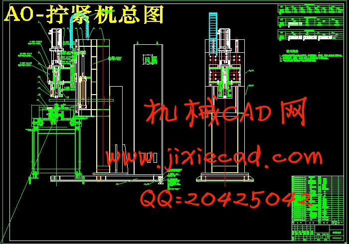
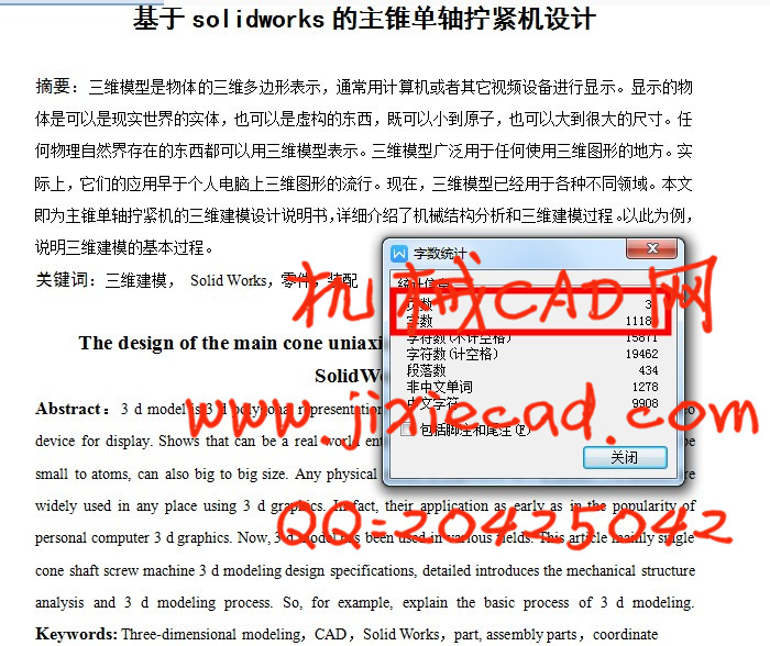
主锥单轴拧紧机设计
摘要:三维模型是物体的三维多边形表示,通常用计算机或者其它视频设备进行显示。显示的物体是可以是现实世界的实体,也可以是虚构的东西,既可以小到原子,也可以大到很大的尺寸。任何物理自然界存在的东西都可以用三维模型表示。三维模型广泛用于任何使用三维图形的地方。实际上,它们的应用早于个人电脑上三维图形的流行。现在,三维模型已经用于各种不同领域。本文即为主锥单轴拧紧机的三维建模设计说明书,详细介绍了机械结构分析和三维建模过程。以此为例,说明三维建模的基本过程。
关键词:零件,装配
The design of the main cone uniaxial tightening machine based on SolidWorks
Abstract:3 d model is 3 d polygonal representation of object, usually use a computer or other video device for display. Shows that can be a real world entity objects, also can be imaginary things, can be small to atoms, can also big to big size. Any physical nature is expressed in 3 d model. 3 d models are widely used in any place using 3 d graphics. In fact, their application as early as in the popularity of personal computer 3 d graphics. Now, 3 d model has been used in various fields. This article mainly single cone shaft screw machine 3 d modeling design specifications, detailed introduces the mechanical structure analysis and 3 d modeling process. So, for example, explain the basic process of 3 d modeling. Keywords: Three-dimensional modeling,CAD,Solid Works,part, assembly parts,coordinate
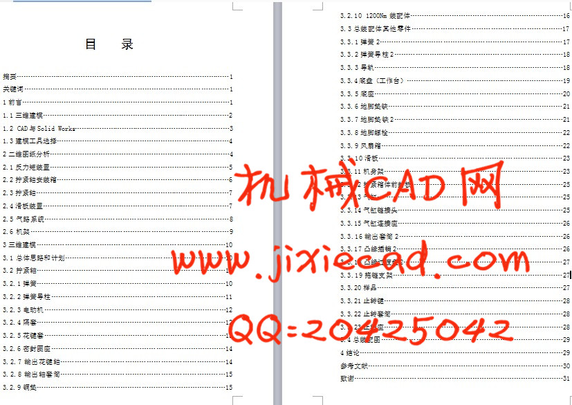
目 录
摘要…………………………………………………………………………………1
关键词……………………………………………………………………………1
1前言………………………………………………………………………………1
1.1三维建模………………………………………………………………………2
1.2 CAD与Solid Works……………………………………………………………3
1.3建模工具选择…………………………………………………………………4
2二维图纸分析……………………………………………………………………4
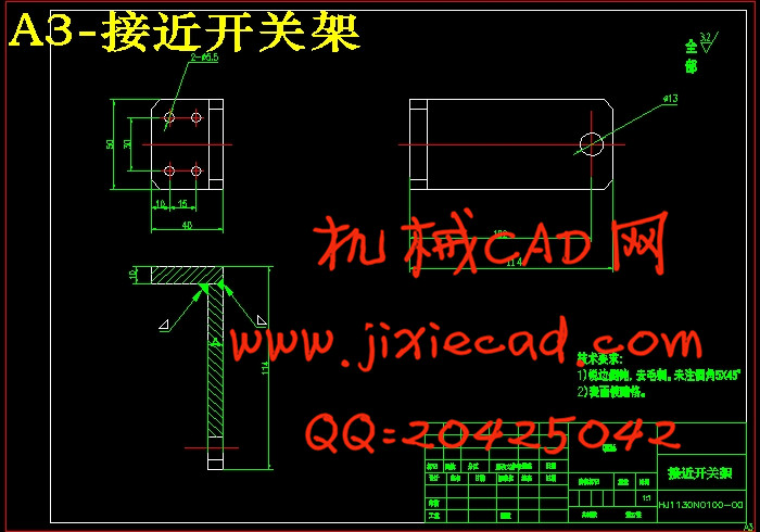
2.1反力矩装置……………………………………………………………………5
2.2拧紧轴安装箱…………………………………………………………………6
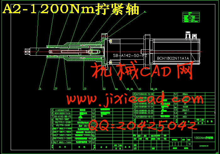
2.3拧紧轴…………………………………………………………………………7
2.4滑板装置………………………………………………………………………7
2.5气路系统……………………………………………………………………8
2.6机架…………………………………………………………………………9
3三维建模………………………………………………………………………10
3.1总体思路和计划……………………………………………………………10
3.2拧紧轴………………………………………………………………………10
3.2.1弹簧………………………………………………………………………10
3.2.2弹簧导柱…………………………………………………………………11
3.2.3电动机……………………………………………………………………12
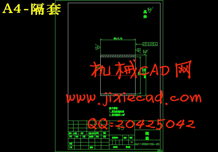
3.2.4隔套………………………………………………………………………12
3.2.5花键套……………………………………………………………………13
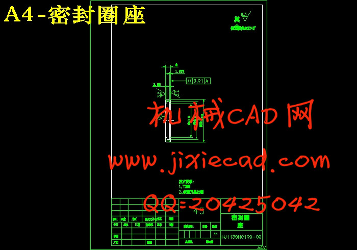
3.2.6密封圈座…………………………………………………………………14
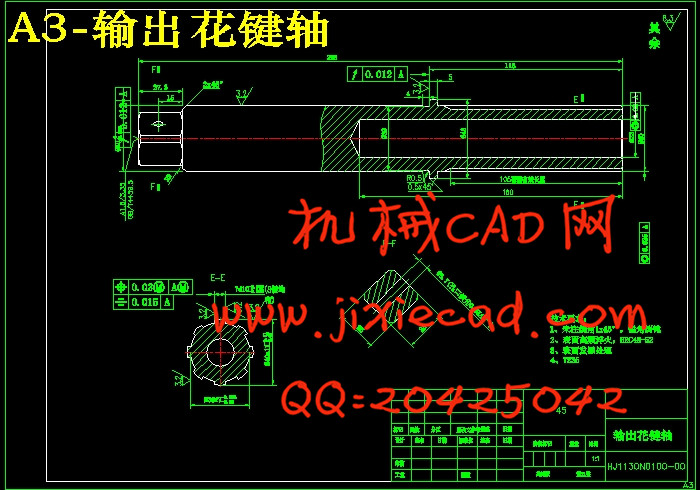
3.2.7输出花键轴……………………………………………………………14
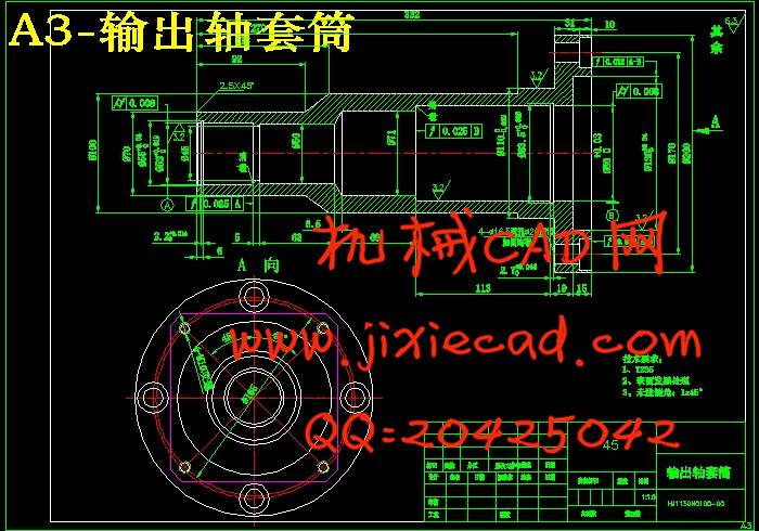
3.2.8输出轴套筒……………………………………………………………15
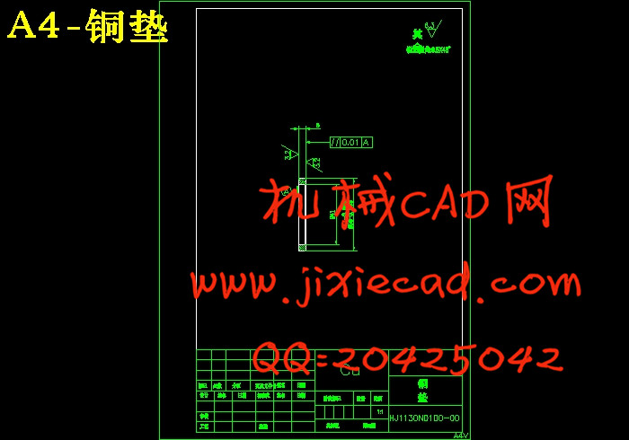
3.2.9铜垫………………………………………………………………………15
3.2.10 1200Nm装配体…………………………………………………………16
3.3总装配体其他零件………………………………………………………17
3.3.1弹簧2……………………………………………………………………17
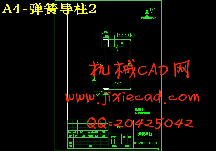
3.3.2弹簧导柱2………………………………………………………………18
3.3.3导轨………………………………………………………………………18
3.3.4底盘(工作台)……………………………………………………………19
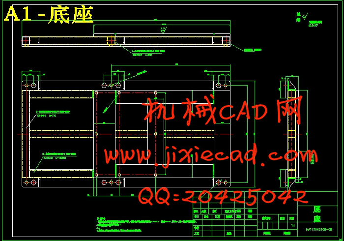
3.3.5底座………………………………………………………………………20
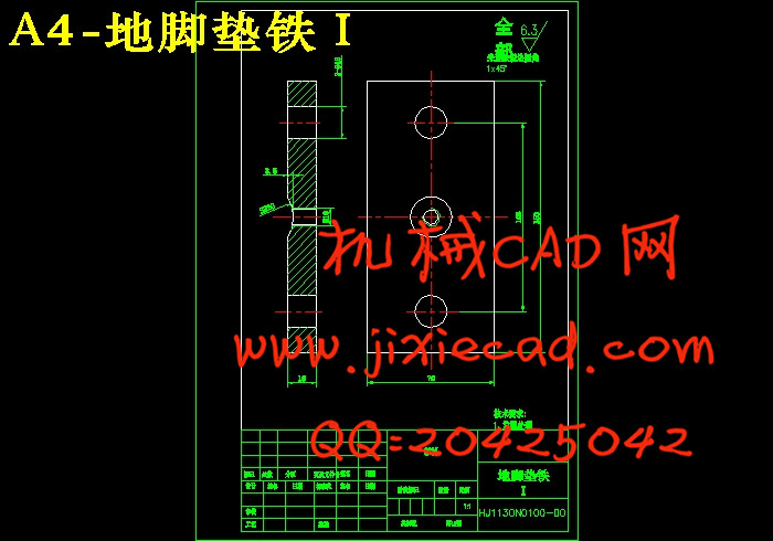
3.3.6地脚垫铁…………………………………………………………………21
3.3.7地脚垫铁2………………………………………………………………21
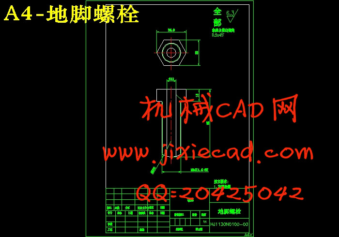
3.3.8地脚螺栓…………………………………………………………………22
3.3.9风扇箱……………………………………………………………………22
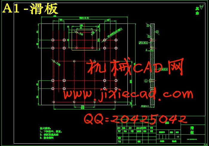
3.3.10滑板……………………………………………………………………23
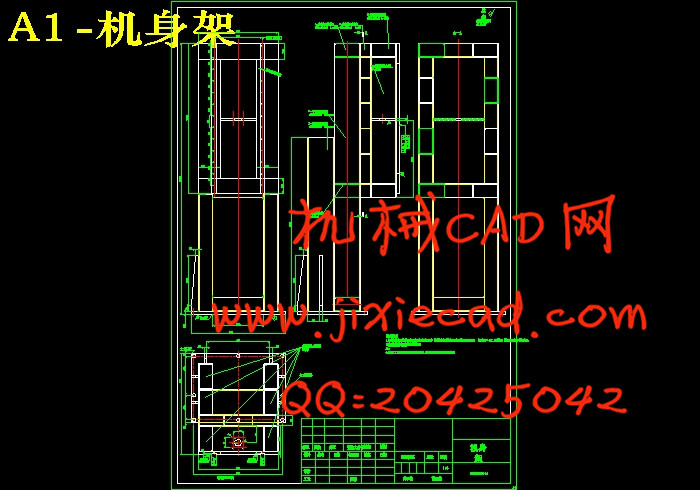
3.3.11机身架……………………………………………………………………23
3.3.12拧紧箱体前封板…………………………………………………………25
3.3.13气缸………………………………………………………………………25
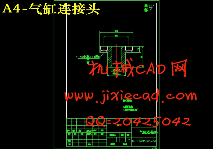
3.3.14气缸链接头………………………………………………………………25
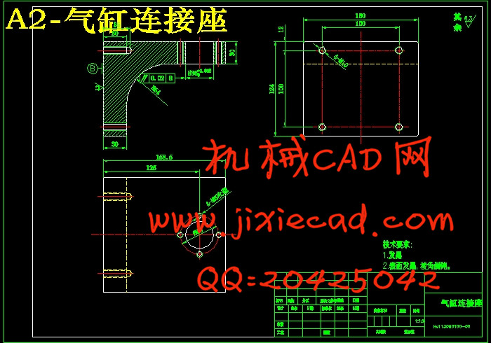
3.3.15气缸连接座………………………………………………………………26
3.3.16输出套筒2……………………………………………………………26
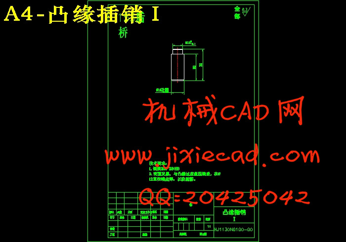
3.3.17凸缘插销2………………………………………………………………26
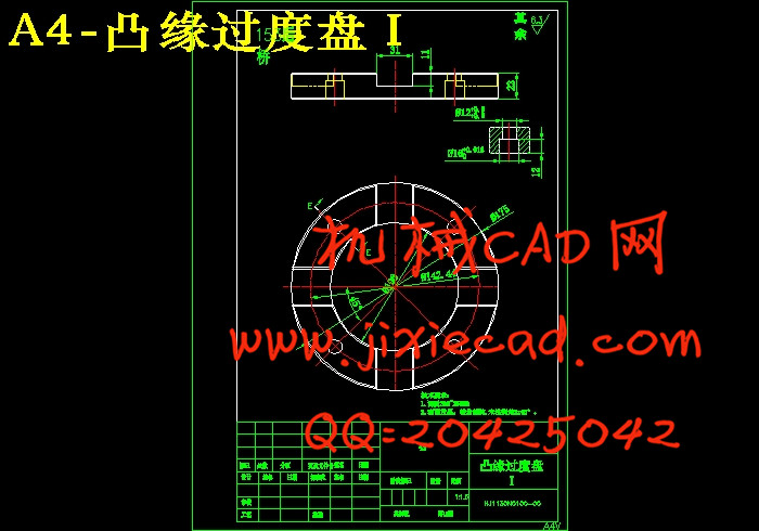
3.3.18凸缘过渡盘2……………………………………………………………27
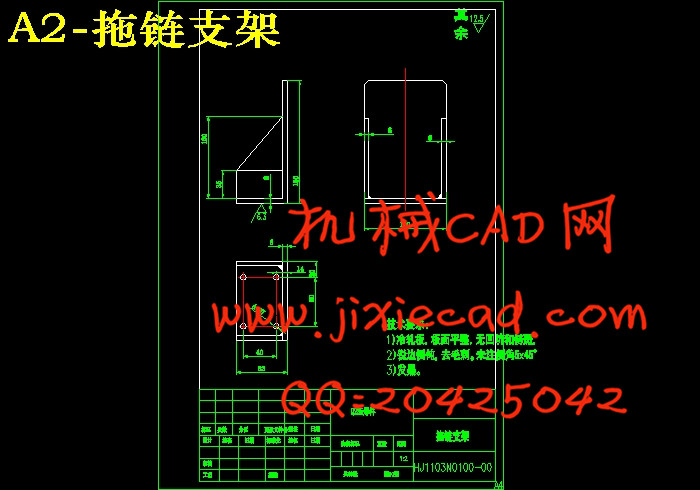
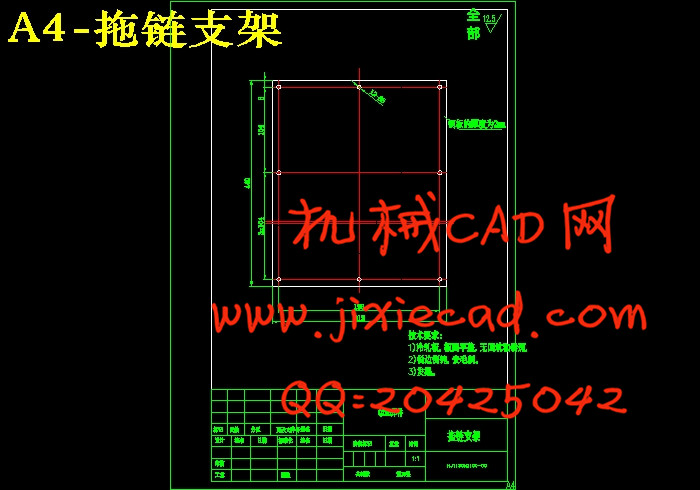
3.3.19拖链支架………………………………………………………………27
3.3.20样品………………………………………………………………………27
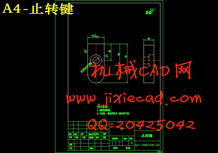
3.3.21止转键……………………………………………………………………28
3.3.22止转套筒…………………………………………………………………28
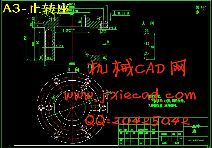
3.3.23止转座……………………………………………………………………28
3.4总装配图……………………………………………………………………29
4结论……………………………………………………………………………29
参考文献…………………………………………………………………………30
致谢………………………………………………………………………………31
摘要:三维模型是物体的三维多边形表示,通常用计算机或者其它视频设备进行显示。显示的物体是可以是现实世界的实体,也可以是虚构的东西,既可以小到原子,也可以大到很大的尺寸。任何物理自然界存在的东西都可以用三维模型表示。三维模型广泛用于任何使用三维图形的地方。实际上,它们的应用早于个人电脑上三维图形的流行。现在,三维模型已经用于各种不同领域。本文即为主锥单轴拧紧机的三维建模设计说明书,详细介绍了机械结构分析和三维建模过程。以此为例,说明三维建模的基本过程。
关键词:零件,装配
The design of the main cone uniaxial tightening machine based on SolidWorks
Abstract:3 d model is 3 d polygonal representation of object, usually use a computer or other video device for display. Shows that can be a real world entity objects, also can be imaginary things, can be small to atoms, can also big to big size. Any physical nature is expressed in 3 d model. 3 d models are widely used in any place using 3 d graphics. In fact, their application as early as in the popularity of personal computer 3 d graphics. Now, 3 d model has been used in various fields. This article mainly single cone shaft screw machine 3 d modeling design specifications, detailed introduces the mechanical structure analysis and 3 d modeling process. So, for example, explain the basic process of 3 d modeling. Keywords: Three-dimensional modeling,CAD,Solid Works,part, assembly parts,coordinate
目 录
摘要…………………………………………………………………………………1
关键词……………………………………………………………………………1
1前言………………………………………………………………………………1
1.1三维建模………………………………………………………………………2
1.2 CAD与Solid Works……………………………………………………………3
1.3建模工具选择…………………………………………………………………4
2二维图纸分析……………………………………………………………………4
2.1反力矩装置……………………………………………………………………5
2.2拧紧轴安装箱…………………………………………………………………6
2.3拧紧轴…………………………………………………………………………7
2.4滑板装置………………………………………………………………………7
2.5气路系统……………………………………………………………………8
2.6机架…………………………………………………………………………9
3三维建模………………………………………………………………………10
3.1总体思路和计划……………………………………………………………10
3.2拧紧轴………………………………………………………………………10
3.2.1弹簧………………………………………………………………………10
3.2.2弹簧导柱…………………………………………………………………11
3.2.3电动机……………………………………………………………………12
3.2.4隔套………………………………………………………………………12
3.2.5花键套……………………………………………………………………13
3.2.6密封圈座…………………………………………………………………14
3.2.7输出花键轴……………………………………………………………14
3.2.8输出轴套筒……………………………………………………………15
3.2.9铜垫………………………………………………………………………15
3.2.10 1200Nm装配体…………………………………………………………16
3.3总装配体其他零件………………………………………………………17
3.3.1弹簧2……………………………………………………………………17
3.3.2弹簧导柱2………………………………………………………………18
3.3.3导轨………………………………………………………………………18
3.3.4底盘(工作台)……………………………………………………………19
3.3.5底座………………………………………………………………………20
3.3.6地脚垫铁…………………………………………………………………21
3.3.7地脚垫铁2………………………………………………………………21
3.3.8地脚螺栓…………………………………………………………………22
3.3.9风扇箱……………………………………………………………………22
3.3.10滑板……………………………………………………………………23
3.3.11机身架……………………………………………………………………23
3.3.12拧紧箱体前封板…………………………………………………………25
3.3.13气缸………………………………………………………………………25
3.3.14气缸链接头………………………………………………………………25
3.3.15气缸连接座………………………………………………………………26
3.3.16输出套筒2……………………………………………………………26
3.3.17凸缘插销2………………………………………………………………26
3.3.18凸缘过渡盘2……………………………………………………………27
3.3.19拖链支架………………………………………………………………27
3.3.20样品………………………………………………………………………27
3.3.21止转键……………………………………………………………………28
3.3.22止转套筒…………………………………………………………………28
3.3.23止转座……………………………………………………………………28
3.4总装配图……………………………………………………………………29
4结论……………………………………………………………………………29
参考文献…………………………………………………………………………30
致谢………………………………………………………………………………31