设计简介
摘要: 这里首先分析了机床的结构与工艺特点,在此基础上对专用机床的配置和夹具进行设计,并且设计了专用机床上刀具的微调装夹装置。实践证明,这种专用机床能够满足批量生产的需要。
本次设计的课题是基于PRO/E立式双轴缸孔半精镗机床总体及刀具设计。该课题来源于江淮动力集团。本次设计分总体设计和刀具设计两个部分。
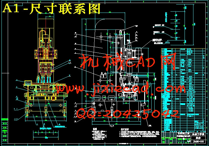
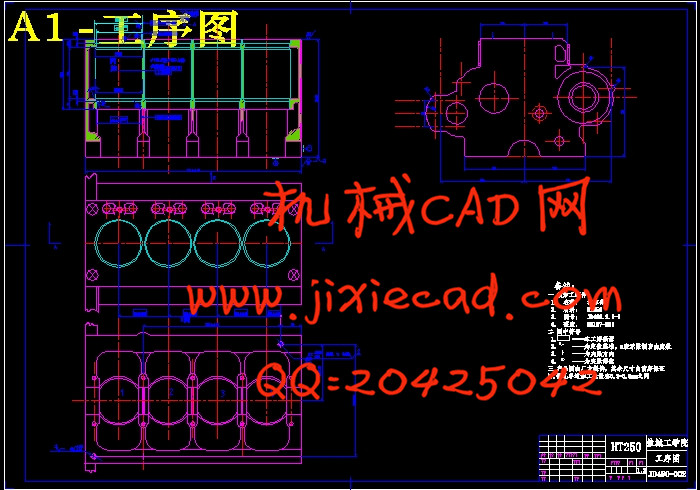
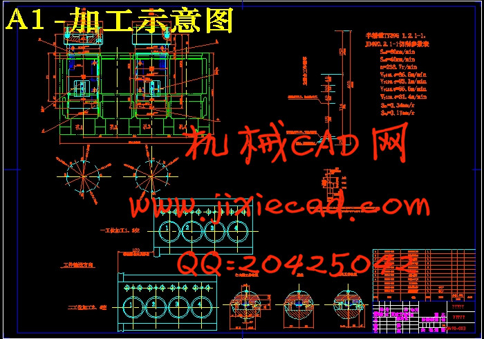
本说明书以设计立式双轴缸孔半精镗组合机床为主线,阐述了刀具的选择、镗削头和夹具设计的过程。在总体设计中,首先是被加工零件的工艺分析,然后是总体方案的论证。在比较了许多方案之后,结合本道工序加工的特点最终选择立式的机床配置型式。再结合本道工序的特点选择刀具。根据选择的切削用量,计算刀具的切削力、切削扭矩、切削功率等,再确定刀具的大小和型式。在确定这些设计计算后,然后是绘制组合机床的“三图一卡”—被加工零件工序图、加工示意图、机床联系尺寸图和生产率计算卡。
关键词: 专用机床;夹具;镗削;刀具
Design of the tool and overall for vertical-biaxial-cylinder semi-fine boring machine based on the platform of PROE
Abstract:This article first analyses the structure and craft character of the Special lathe.And then based on the analyses,the disposition and the clamp are design.This disposion and the clamp are designed.This article also designs a microadjustable device for cutter in the special lathe.According to the practice,this special lathe can meet the need of the batch producting.
The design is based on the platform of PRO/E,the task force comes form Jianghuai Group.The design includs of the overall design,fixture design,boring head design,tool design.
The main line of the statement is to design vertical cylinder-half combination of fine boring machine, described the choice of cutting tools, boring head and fixture design process. In the design, the first is the technology analysis of the processed parts, then demonstration of the overall plan. After comparing with the numbers of programmes and combining the processing features of this process,we choose the vertical lathe at last. I chosed tool that combined with the characteristics of this procedure. According to the choice of cutting amount , cutting force and cutting torque, cutting power and so on, than to determine the size and type of tool. In determining the design and calculation, and drawing "three figures one card"of the combination lathe - was the processing figure of the processd parts, processing diagram, size map of machine and the productivity calculation card.
Key words: Special lathe; Clamp; Bore pare;Tool
目 录
1前言 1
2组合机床总体设计 3
2.1 总体方案的确定 3
2.1.1 工艺方案的拟订 3
2.1.2 定位基准的选择 4
2.1.3 机床配置型式的选择 4
2.1.4 滑台型式的选择 4
2.2 切削用量及选择刀具的确定 5
2.2.1 切削用量的选择 5
2.2.2 切削力、切削扭矩及切削功率的计算 6
2.2.3 刀具结构的选择 9
2.3 组合机床总体设计—“三图一卡” 9
2.3.1 被加工零件工序图 9
2.3.2 加工示意图 10
2.3.3 机床联系尺寸总图 11
2.3.4 生产率计算卡 12
3 组合镗刀设计 16
3.1 刀具设计概述 16
3.2 组合镗刀工作原理 16
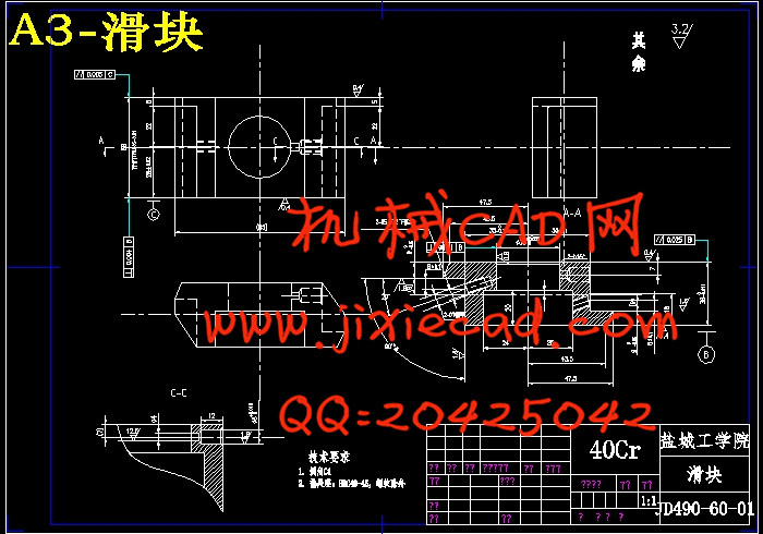
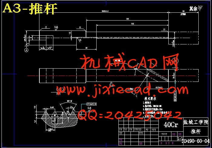
3.3 推杆与滑块工作原理 17
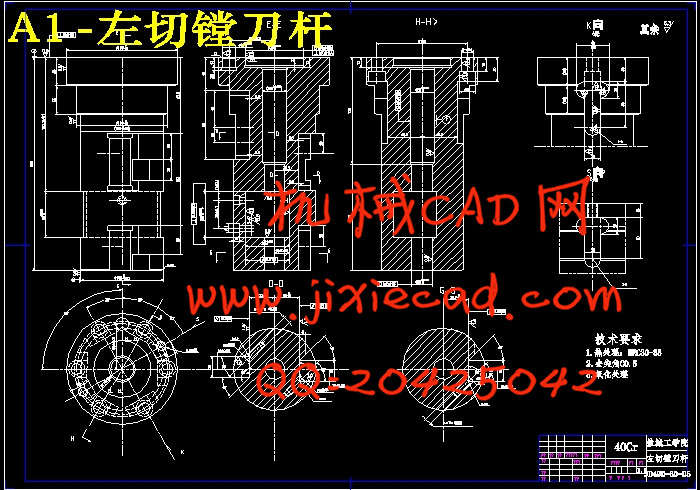
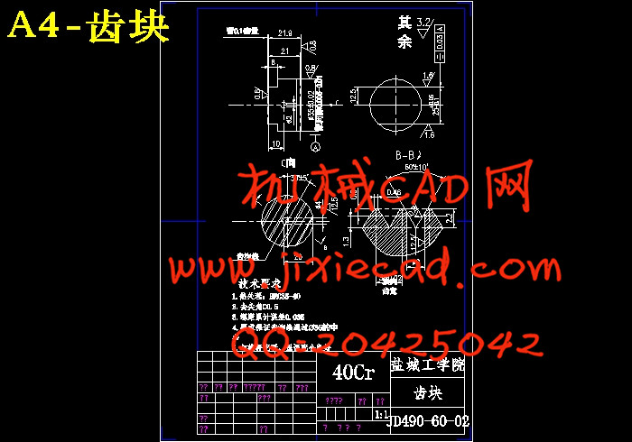
3.4 镗刀设计 19
4 结论 25
文 献 资 料 26
致 谢 27
本次设计的课题是基于PRO/E立式双轴缸孔半精镗机床总体及刀具设计。该课题来源于江淮动力集团。本次设计分总体设计和刀具设计两个部分。
本说明书以设计立式双轴缸孔半精镗组合机床为主线,阐述了刀具的选择、镗削头和夹具设计的过程。在总体设计中,首先是被加工零件的工艺分析,然后是总体方案的论证。在比较了许多方案之后,结合本道工序加工的特点最终选择立式的机床配置型式。再结合本道工序的特点选择刀具。根据选择的切削用量,计算刀具的切削力、切削扭矩、切削功率等,再确定刀具的大小和型式。在确定这些设计计算后,然后是绘制组合机床的“三图一卡”—被加工零件工序图、加工示意图、机床联系尺寸图和生产率计算卡。
关键词: 专用机床;夹具;镗削;刀具
Design of the tool and overall for vertical-biaxial-cylinder semi-fine boring machine based on the platform of PROE
Abstract:This article first analyses the structure and craft character of the Special lathe.And then based on the analyses,the disposition and the clamp are design.This disposion and the clamp are designed.This article also designs a microadjustable device for cutter in the special lathe.According to the practice,this special lathe can meet the need of the batch producting.
The design is based on the platform of PRO/E,the task force comes form Jianghuai Group.The design includs of the overall design,fixture design,boring head design,tool design.
The main line of the statement is to design vertical cylinder-half combination of fine boring machine, described the choice of cutting tools, boring head and fixture design process. In the design, the first is the technology analysis of the processed parts, then demonstration of the overall plan. After comparing with the numbers of programmes and combining the processing features of this process,we choose the vertical lathe at last. I chosed tool that combined with the characteristics of this procedure. According to the choice of cutting amount , cutting force and cutting torque, cutting power and so on, than to determine the size and type of tool. In determining the design and calculation, and drawing "three figures one card"of the combination lathe - was the processing figure of the processd parts, processing diagram, size map of machine and the productivity calculation card.
Key words: Special lathe; Clamp; Bore pare;Tool
目 录
1前言 1
2组合机床总体设计 3
2.1 总体方案的确定 3
2.1.1 工艺方案的拟订 3
2.1.2 定位基准的选择 4
2.1.3 机床配置型式的选择 4
2.1.4 滑台型式的选择 4
2.2 切削用量及选择刀具的确定 5
2.2.1 切削用量的选择 5
2.2.2 切削力、切削扭矩及切削功率的计算 6
2.2.3 刀具结构的选择 9
2.3 组合机床总体设计—“三图一卡” 9
2.3.1 被加工零件工序图 9
2.3.2 加工示意图 10
2.3.3 机床联系尺寸总图 11
2.3.4 生产率计算卡 12
3 组合镗刀设计 16
3.1 刀具设计概述 16
3.2 组合镗刀工作原理 16
3.3 推杆与滑块工作原理 17
3.4 镗刀设计 19
4 结论 25
文 献 资 料 26
致 谢 27