设计简介
摘 要
变速器用来改变发动机传到驱动轮上的转矩和转速,目的是在原地起步,爬坡,转弯,加速等各种行驶工况下,使汽车获得不同的牵引力和速度,同时使发动机在最有利工况范围内工作。变速器设有空挡和倒挡。需要时变速器还有动力输出功能。
因为变速箱在低档工作时作用有较大的力,所以一般变速箱的低档都布置靠近轴的后支承处,然后按照从低档到高档顺序布置各档位齿轮。这样做既能使轴有足够大的刚性,又能保证装配容易。变速箱整体结构刚性与轴和壳体的结构有关系。一般通过控制轴的长度即控制档数,来保证变速箱有足够的刚性。
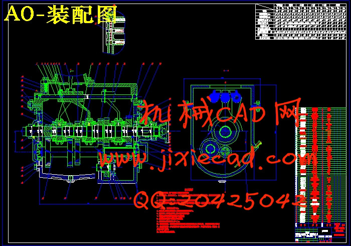
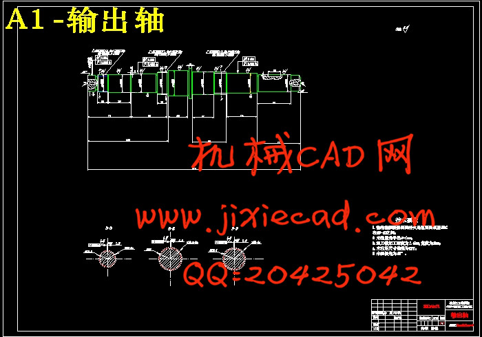
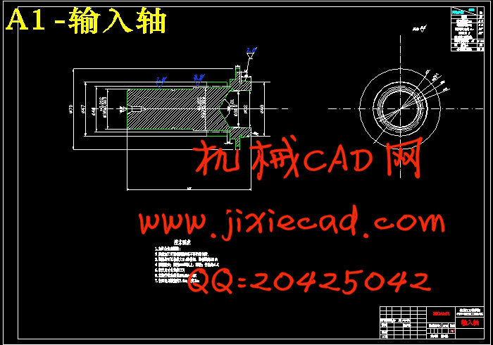
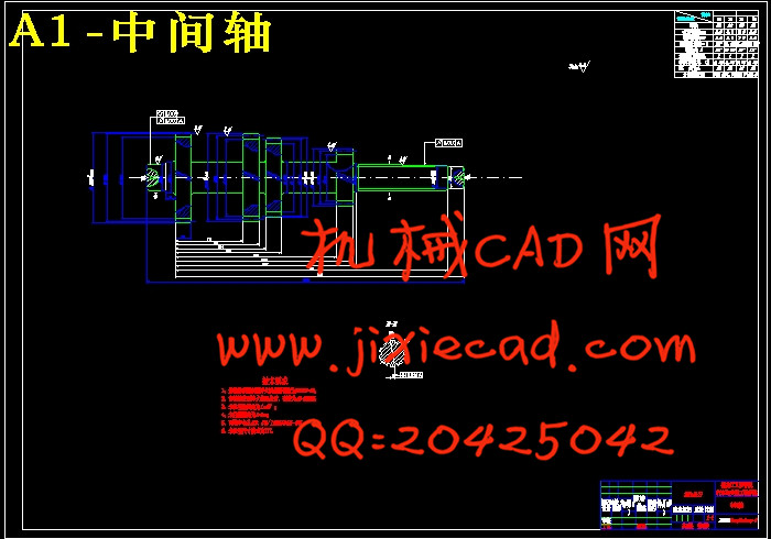
本文设计研究了三轴式五挡手动变速器,对变速器的工作原理做了阐述,变速器的各挡齿轮和轴做了详细的设计计算,并进行了强度校核,对一些标准件进行了选型。变速器的传动方案设计并讲述了变速器中各部件材料的选择。
关键字:变速器;设计;齿轮;轴;校核
ABSTRACT
Transmission to change the engine reached on the driving wheel torque and speed, is aimed at marking start, climbing, turning, accelerate various driving conditions, the car was different traction and speed Meanwhile engine in the most favorable working conditions within the scope of the work. And the trans mission in neutral gear with reverse gear. Transmission also need power output function.
Gearbox because of the low-grade work at a larger role, In general, the low-grade gearbox layout are close to the axis after support, Following from low-grade to high-grade order of the layout of stalls gear. This will not only allow axis are large enough for a rigid, but also ensures easy assembly. Gear box overall structure and rigid axle and the shell structure of relations. Generally through the control shaft length control over several stalls to ensure that adequate gear box rigid.
This paper describes the design of three-axis five block manual tran mission, the transmission principle of work elaborated, Transmission of the gear shaft and do a detailed design, and the intensity of a school. For some standard parts for the selection. Transmission Trans mission program design. A brief description of the trans mission of all components of the material choice.
Keywords : Transmission; Design; Gear; Axis;Checking
摘要 I
ABSTRACT II
第1章 绪论 1
1.1选题的背景 1
1.2目的及意义 2
第2章 总体方案设计 3
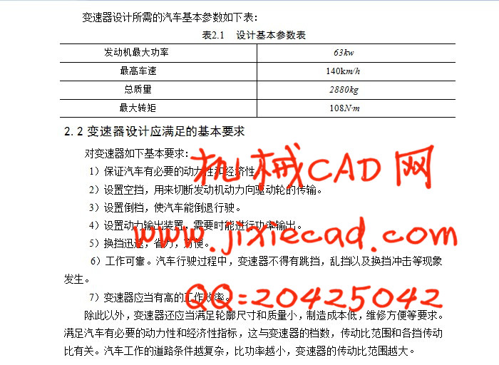
2.1汽车参数的选择 3
2.2变速器设计应满足的基本要求 3
2.3传动机构布置方案分析 3
2.3.1固定轴式变速器 3
2.3.2倒档布置方案 4
2.3.3其它问题 6
2.4齿轮形式 7
2.5换挡机构形式 7
2.6变速器轴承 8
2.7本章小结 9
第3章 变速器设计和计算 10
3.1档数 11
3.2传动比范围 11
3.3各档传动比的确定 11
3.3.1主减速器传动比的确定 11
3.3.2最低档传动比的确定 12
3.3.3各档传动比的确定 13
3.3.4中心距的选定 13
3.3.5变速器的外形尺寸 14
3.4齿轮参数 14
3.4.1模数的选取 14
3.4.2压力角 15
3.4.3螺旋角 15
3.4.4齿宽 16
3.4.5齿顶高系数 17
3.4.6变位系数的选择原则 17
3.5各档齿数的分配 18
3.5.1确定一档齿轮的齿数 18
3.5.2对中心距进行修正 20
3.5.3确定常啮合传动齿轮副齿数及变位系数 20
3.5.4确定其他各档齿数及变位系数 21
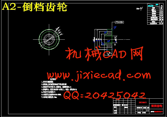
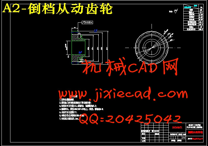
3.5.5确定倒档齿轮齿数及变位系数 26
3.6本章小结 28
第4章 变速器的校核 29
4.1齿轮的损坏形式 29
4.2 齿轮强度计算 28
4.2.1齿轮弯曲强度计算 28
4.2.2齿轮接触应力计算 30
4.3轴的结构设计 32
4.4轴的强度验算 33
4.4.1轴的刚度的计算 33
4.4.2轴的强度的计算 38
4.5轴承寿命计算 41
4.6本章小结 44
第5章 同步器的设计 45
5.1 锁销式同步器 45
5.1.1锁销式同步器结构 45
5.1.2锁销式同步器工作原理 45
5.2锁环式同步器 46
5.2.1锁环式同步器结构 46
5.2.2锁环式同步器的工作原理 46
5.2.3锁环式同步器主要尺寸的确定 47
5.3 本章小结 49
第6章 变速器操纵机构 50
6.1直接操纵手动换挡变速器 50
6.2远距离操纵手动换挡变速器 50
6.3本章小结 51
结论 52
参考文献 53
致谢 54