设计简介
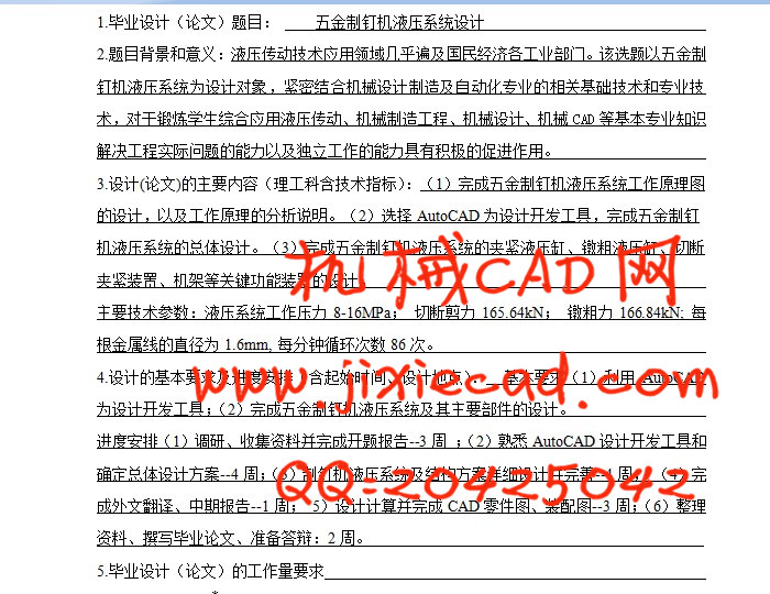
五金制钉机液压系统设计
摘 要
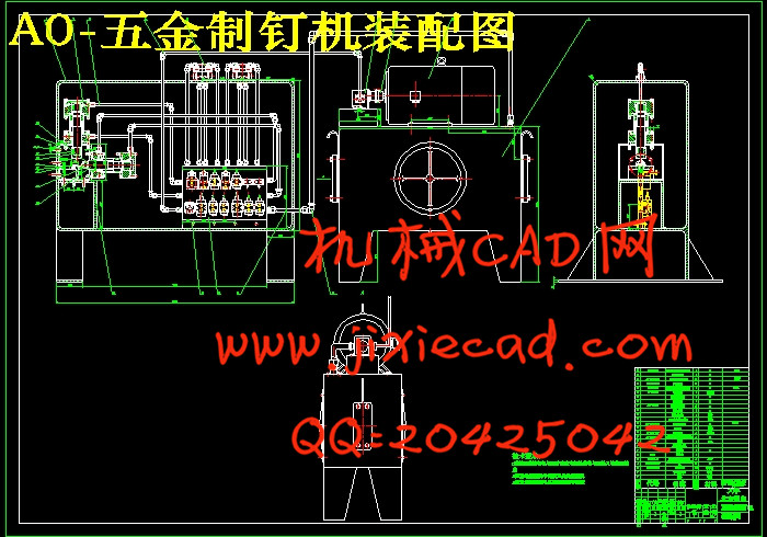
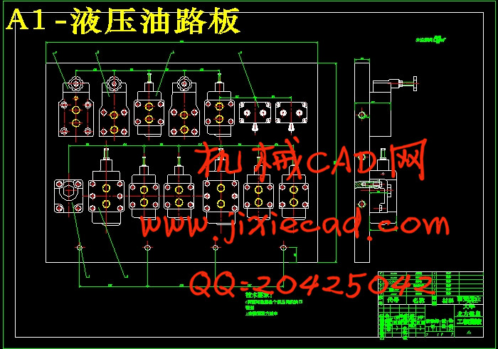
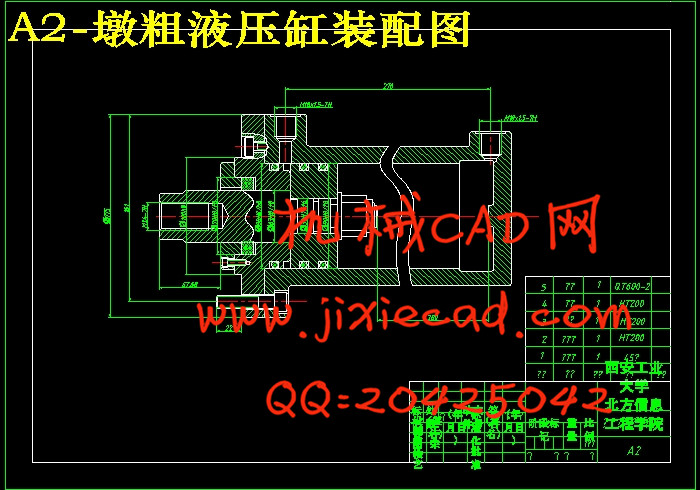
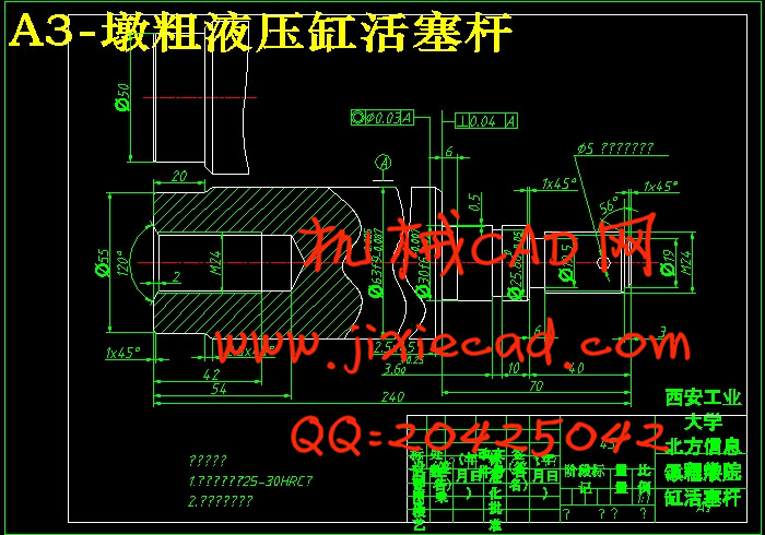
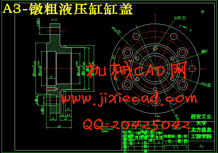
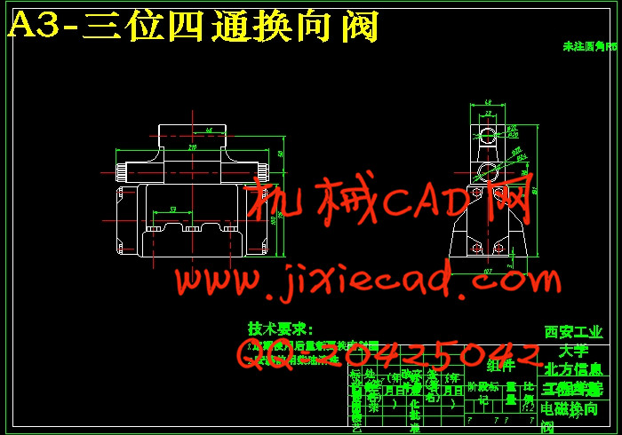
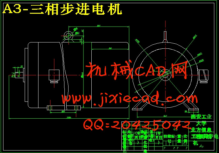
制钉机由于其效率高,使钉子受力均匀、一致、使用方便等优点而广泛用于包装、广告装饰及家具制造、制鞋业等方面。而作为其“子弹” 的排钉,也就有了大量的需求。本文分析了制钉机的方便快捷的工作过程,及钉子的大量需求必定有着好的市场前景。制钉机的制作过程包括:切断钉子的切断液压缸,镦粗钉子的镦粗液压缸,将钉子镦粗与夹紧的切断夹紧装置。针对切断液压缸与镦粗液压缸的设计是实现整个制钉机工作的基础,重点设计了切断液压缸与夹紧液压缸的结构、切断夹紧装置、机架。并根据系统压力、流量选择了液压阀、电机、泵。本文的设计能够满足制钉机要求(系统压力16MPa,切断力与夹紧力都满足题目所要求的16564N和16684N,每分钟循环86次)具有方便快捷制钉的特点。
关键词:五金制钉机;液压元件;切断液压缸;镦粗液压缸;机架
The Design Of Hydraulic System For Nail-making Machine
摘 要
制钉机由于其效率高,使钉子受力均匀、一致、使用方便等优点而广泛用于包装、广告装饰及家具制造、制鞋业等方面。而作为其“子弹” 的排钉,也就有了大量的需求。本文分析了制钉机的方便快捷的工作过程,及钉子的大量需求必定有着好的市场前景。制钉机的制作过程包括:切断钉子的切断液压缸,镦粗钉子的镦粗液压缸,将钉子镦粗与夹紧的切断夹紧装置。针对切断液压缸与镦粗液压缸的设计是实现整个制钉机工作的基础,重点设计了切断液压缸与夹紧液压缸的结构、切断夹紧装置、机架。并根据系统压力、流量选择了液压阀、电机、泵。本文的设计能够满足制钉机要求(系统压力16MPa,切断力与夹紧力都满足题目所要求的16564N和16684N,每分钟循环86次)具有方便快捷制钉的特点。
关键词:五金制钉机;液压元件;切断液压缸;镦粗液压缸;机架
The Design Of Hydraulic System For Nail-making Machine
Abstract
Nail-making machine because of its high efficiency,make the nails force uniform, consistent, easy to be used and so on, nail-making machine is widely used in packaging, advertising and decorating furniture by manufacturers, the footwear industry and so on. As part of its "bullets" of the nails, there will have a huge demand. This paper analyzes the nail-making machine of the simple facilitate the work of engineering, and nails of a large number of requirements must have good market prospects. Nail-making machine of the production process, including: the hydraulic cylinders cut the nails off, the hydraulic cylinder nails upsetting , upsetting the nails with the clamping clamping cut device. For cutting off for upsetting hydraulic cylinders and hydraulic cylinder design, the basis of nail-making machine is to achieve the whole work. Focus on the design of the hydraulic cylinders and clamping off hydraulic cylinder structure, the cut off the clamps, the rack. In accordance with the system pressure, flow, choose the hydraulic valve, motor, pump. This article is designed to meet the requirements of nail-making machine(system pressure of 16MPa, cutting force and clamping force are required to meet the subject 16564N, and 16684N, the cycle 86 times per minute)It is convenient features of nail-making.
Key Words: Nail-making machine; Hydraulic Components; The cut off hydraulic cylinder; Hydraulic cylinder upsetting
目 录
1 绪 论 1
1.1题目背景及研究意义 1
1.2国内外研究情况 1
2 研究方案及系统原理 3
2.1液压系统的组成及其作用 3
2.2制钉机液压系统 3
2.2.1主机的功能结构 3
2.2.2液压系统及其工作原理 5
2.2.3技术特点 6
2.2.4技术参数 7
3 液压系统方案设计 8
3.1确定液压泵的类型及调速方式 8
3.2选用执行元件 8
3.3快速运动回路和速度换接回路 8
3.4换向回路的选择 8
4 液压系统设计计算 9
4.1系统液压可以完成的工作循环 9
4.2 液压执行元件的配置 9
4.3 负载分析计算 9
4.4 确定液压缸主要尺寸 10
4.4.1确定垂直液压缸的主要结构尺寸 10
4.4.2确定水平液压缸的主要结构尺寸 10
4.5活塞杆强度计算 11
4.6液压缸活塞的推力及拉力计算 11
4.6.1垂直液压缸 12
4.6.2水平液压缸 12
4.7活塞杆最大容许行程 13
4.8液压缸缓冲装置计算 14
4.8.1设置缓冲装置的目的和条件 14
4.8.2缓冲装置的原理及要求 14
4.8.3缓冲装置的类型 14
4.9液压缸长度及壁厚的确定 15
4.9.1液压缸内径计算 15
4.9.2液压缸壁厚计算 15
4.10液压缸筒与缸底的连接计算 16
5 元件选型及系统压力验算 18
5.1液压泵及其驱动电动机的选择 18
5.1.1计算液压泵的最大工作压力 19
5.1.2计算液压泵的最大流量 20
5.1.3选择液压泵的规格 21
5.1.4计算液压泵的驱动功率并选择原动机 21
5.2其他液压元件的选择 22
5.2.1液压阀及过滤器的选择 22
5.2.2油管的选择 23
5.2.3油箱容积的确定 24
5.3 液压系统压力损失验算 24
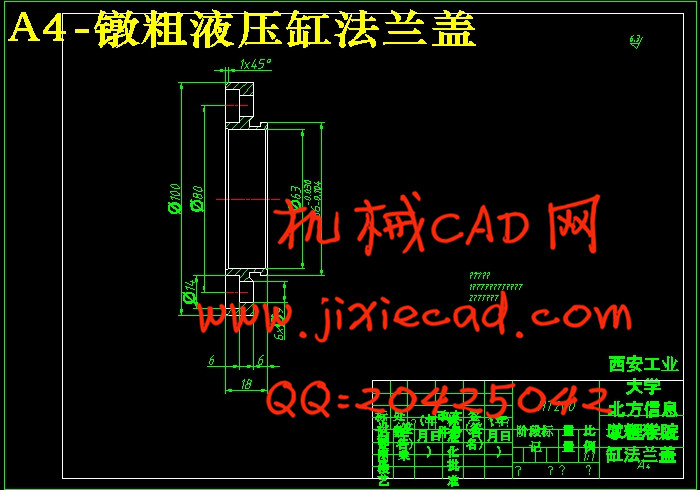
6 液压缸各部分的结构、材料及制造技术条件 26
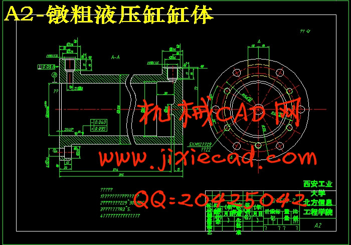
6.1缸体 26
6.1.1缸体端部连接结构 26
6.1.2缸体材料 26
6.1.3缸体技术条件 26
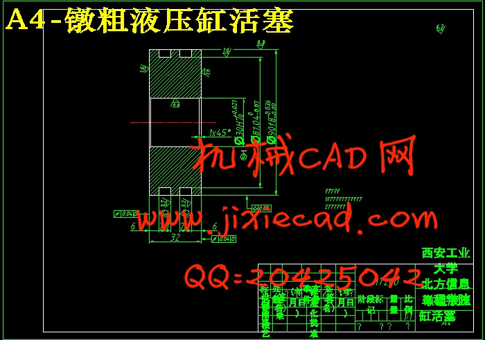
6.2活塞 27
6.2.1活塞与活塞杆的联接型式 27
6.2.2活塞的密封 27
6.2.3活塞的材料 27
6.2.4活塞的技术要求 27
6.3活塞杆 28
6.3.1端部结构 28
6.3.2端部尺寸 28
6.3.3活塞杆结构 28
6.3.4活塞杆的技术要求 29
6.4活塞杆的导向、密封和防尘 29
6.4.1导向套 29
6.4.2活塞杆的密封与防尘 30
6.5液压缸安装联接部分的型式及尺寸 30
6.5.1液压缸进出油口接头的联接螺纹尺寸 30
6.5.2液压缸为单耳环型安装的主要尺寸 30
6.5.3活塞式液压缸端部型式及尺寸 30
6.5.4缸盖的材料 30
6.6液压缸的排气装置 31
6.7缓冲调节阀 31
6.8单向阀 31
7 总结 32
参考文献 33
致 谢 34