设计简介
卧式双面切槽精镗摇臂轴孔组合机床总体设计
摘要:本机床所加工零件为水泵壳体,其主要特点为壳体表面孔比较多且加工精度要求较高,形状结构复杂。为了满足加工技术要求,进行本组合机床总体设计。本文详述卧式双面切槽精镗摇臂轴孔组合机床的总体设计的方法步骤,包括壳体待加工孔、槽的工艺性和技术性分析,根据分析采用一面两销(端面和两定位孔)定位方式,液压夹紧方式并进行位基准的分析;壳体加工工艺路线采用先镗孔,后切槽的方式;配置型式设计为卧式双面,布局结构为左端镗孔,右端切槽;根据切削力的计算选择西德标准DSS镗削头,SEHY400,SEME400型号滑台;两侧底座选用STH400(高560)型号,中间底座和夹具部分为专用设计;本组合机床“三图一卡”的绘制。
本机床总体设计结果和结论:
该组合机床的设计,满足壳体三个孔一个槽的加工精度要求;其加工总时间约为3.3分钟,满足4.5分钟的要求,节约加工时间,为大规模的实际生产奠定了基础。
关键词:组合机床 卧式 双面 精镗 切槽 总体设计
Overall Design of Horizontal Two-side Grooving and Fine Boring Rocker Arm Axle Hole Modular Machine Tool
Abstract:The processing parts of the machine are pump castings,.the main features are the more shell holes,higher machining precision,complex shapes.To meet the requirements of the technology,the modular machine tool is designed.
It describes the steps of the overall design of horizontal two-side grooving and fine boring rocker arm axle hole modular machine tool,including the machined shell hole,grove technology and technical analysis,based on an analysis,we adopted the side of two-pin(face and two positioning holes) positioning method,hydraulic clamping means and positioning benchmarking analysis;the case processing line using the way of boring firstly,and notching secondly;configuration type designed for horizontal two-side ,boring layout structure for the left hole,right side notch;according to the calculation of cutting force,we choice DSS boring head ,SEHY400,SEME400 type slide,at the standard West Germany;both sides of the base used STH400(high 560)models,the middle part of the base ang dedicated fixture design belong to special design;the combination of machine tool “3 Figure 1 Card” draw.
The results and conclusions of the overall design of this machine :
The design of the modular machine meets the three holes of a tank shell processing accuracy;its total processing time is about 3.3 minutes,which meet the 4.5minutes requirements,save processing time and make a great basis on the actual production.
Key words:Mdular Machine Tool; Horizontal; Two-side; Fine Boring; Grooving; Overall Designing
目 录
中文摘要、关键字……………………………………………………………………………1
英文摘要、关键字……………………………………………………………………………2
引言 ……………………………………………………………………………………………3
第1章 组合机床总体设计绪论…………………………………………………………4
1.1 课题的背景和意义……………………………………………………………………4
1.2 组合机床的组成及其特点……………………………………………………………4
1.3 组合机床的现状………………………………………………………………………5
1.4 论文的主要内容………………………………………………………………………6
第2章 组合机床工艺方案的制定………………………………………………………7
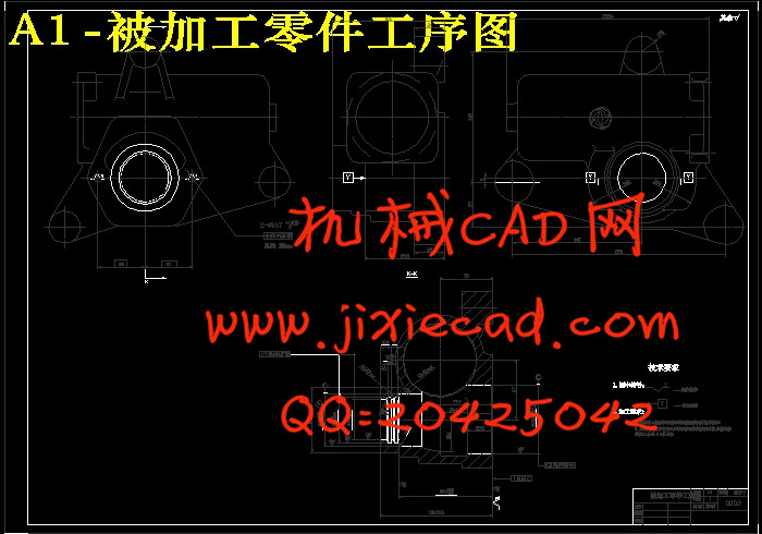
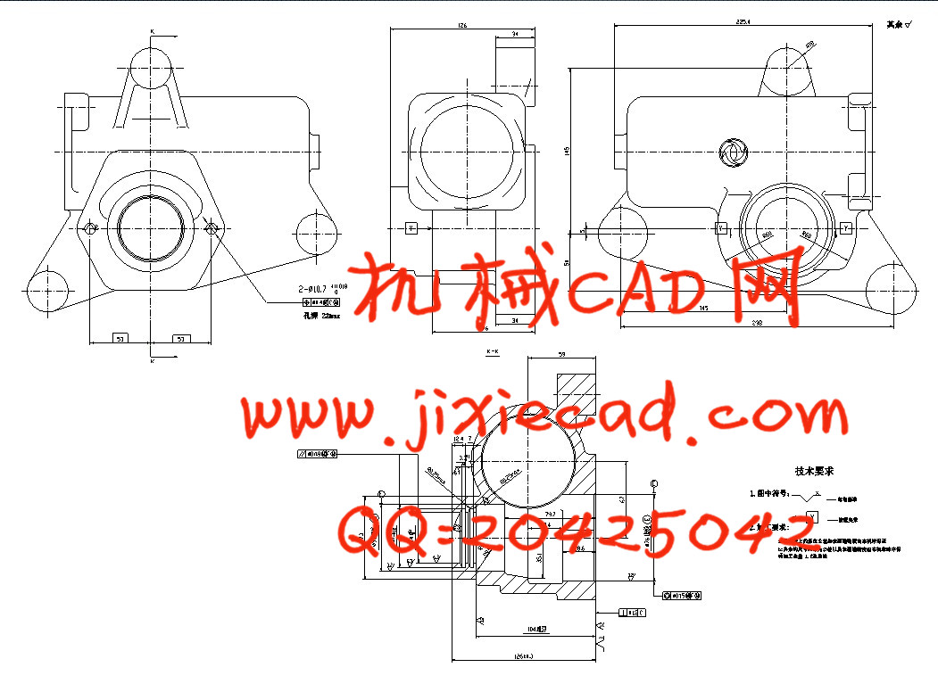
2.1 被加工零件的特点及工艺分析………………………………………………………7
2.1.1 零件技术参数………………………………………………………………………7
2.1.2 技术要求……………………………………………………………………………9
2.1 3 生产纲领分析状……………………………………………………………………9
2.1.4 初步拟定工艺方案…………………………………………………………………9
2.2 选择定位基面,确定定位、夹紧方式……………………………………………10
2.2.1 选择定位基面,确定定位、夹紧方式……………………………………………10
2.2.2 基准重合问题……………………………………………………………………10
2.2.3 工件定位基面和定位方法的选择………………………………………………10
2.2.4 夹紧力问题………………………………………………………………………11
2.3 壳体加工工艺方案的分析及制定…………………………………………………11
2.4 确定切削用量及刀具………………………………………………………………12
2.4.1 刀具的选择………………………………………………………………………13
2.4.2 切削用量的确定及切削力,功率的计算………………………………………13
2.5 组合机床配置型式的选择…………………………………………………………16
2.6 组合机床的机床布局及结构说明…………………………………………………16
第3章 组合机床动力部件的选择………………………………………………………18
第4章 被加工零件工序图………………………………………………………………20
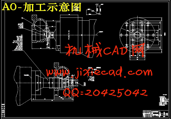
第5章 组合机床加工示意图…………………………………………………………21
5.1 加工示意图的作用…………………………………………………………………21
5.2 加工示意图的内容…………………………………………………………………21
5.3 加工示意图的画法及注意事项……………………………………………………22
5.4 导向结构的选择……………………………………………………………………22
5.5 确定主轴尺寸及外伸长度…………………………………………………………23
5.6 选择接杆……………………………………………………………………………23
5.7 确定动力部件的工作循环及工作行程……………………………………………24
5.7.1 工作进给长度的确定……………………………………………………………24
5.7.2 快速引进长度的确定……………………………………………………………25
5.7.3 快速退回长度的确定……………………………………………………………25
5.7.4 确定动力部件总行程的长度……………………………………………………25
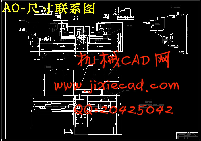
第6章 组合机床联系尺寸图…………………………………………………………27
6.1 机床联系尺寸图作用………………………………………………………………27
6.2 机床联系尺寸图的内容……………………………………………………………27
6.3 绘制机床尺寸联系总图应考虑的主要问题………………………………………27
6.3.1 机床装料高度的确定……………………………………………………………27
6.3.2 夹具轮廓尺寸的确定……………………………………………………………27
6.3.3 中间底座尺寸的确定……………………………………………………………28
6.3.4 机床分组 ………………………………………………………………………… 28
第7章 组合机床生产率计算卡…………………………………………………………29
结论……………………………………………………………………………………………31
致谢……………………………………………………………………………………………32
参考文献………………………………………………………………………………………33
附录1:生产率计算卡 ……………………………………………………………………34