设计简介
卧式双面28轴组合钻床左主轴箱设计
摘 要
机械制造设备的发展是机械工业最主要的环节,目前,机械加工对精度要求越来越高,机械工厂为了降低加工成本,提高加工质量,致使组合机床在制造业中应用越来越广泛,并已显示出巨大的优势。组合机床主要是保证被加工零件的尺寸精度和位置精度要求,高速高效的完成对缸体的加工。在组合机床的设计中,主轴箱加工工艺是关键。绘制主轴箱设计原始移居图,拟定主轴箱的传动路线,应用最优化方法布置齿轮,确定传动参数,绘制主轴箱装配图、箱体补充加工图,并进行轴、齿轮等零件的强度校核。
组合机床主轴箱的基础环节是绘制主轴箱树形图,主轴箱树形图实际上是借鉴了通用机床主传动系统设计中使用的转速图、结构图经演化而来。由于主轴箱传动系统是一个原动件带动多个从动件,没有变速机构,而传动路线条数却很多,出现许多分支。从图形上看,驱动轴相当于树根,各主轴及油泵轴均为末端件,相当于各条树枝的末梢,因此形象地命名为“树形图”。
关键词:组合机床,主轴箱,“三图一卡”,“树形图”
Horizontal double 28 shaft combination drilling machine left spindle box design
Abstract
Machinery manufacturing equipment is the development of the machinery industry the most main link, at present, mechanical processing to the precision requirement more and more high, machinery factory in order to lower manufacturing costs, improve the machining quality, the combination machine tools in the manufacturing industry is more and more extensive application, and has shown great advantage. Combination machine tools is mainly by the size of the processing components to ensure the precision and location accuracy, high speed and high efficient to the finish of machining. In the design of the combination machine tools, spindle box processing technology is the key. Draw spindle box design original moved to figure, draws up the spindle box transmission line, application optimization methods decorate gear, sure drive parameters and draw the spindle box, box added processing chart assembly drawings, and axle, gears and parts of intensity.
Combination machine tools spindle box foundation link is drawing spindle box tree structures, spindle box tree structures is actually lessons from the general machine main transmission system used in the design of the speed diagram, the structure of the evolution. Due to the spindle box transmission system is a former move a drive more follower, no speed changing institutions, and transmission line number but many article, appear many branches. From graphics, it is equivalent to the roots of the drive shaft, the spindle and oil pump shaft are at the end of a thing, which is equivalent to the various peripheral branches, so the image of the named "tree structures".
Key words: transfer and unit machine , Headstock , a three charts card Trees
目录
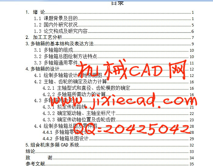
1. 绪 论 1
1.1 课题背景及目的 1
1.2 国内外研究状况 5
1.3 论文构成及研究内容 6
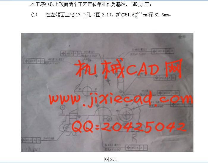
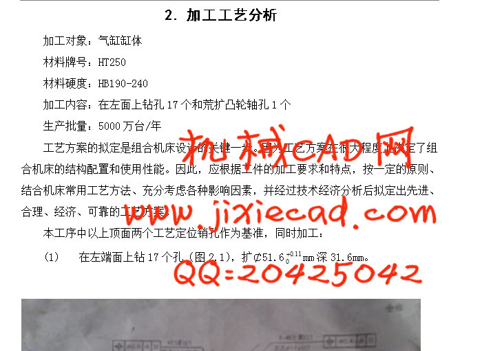
2. 加工工艺分析 7
3.多轴箱的基本结构及表达方法 9
3.1 多轴箱的组成 10
3.2 多轴箱总图绘制方法特点 10
3.3 多轴箱通用零件 11
4.多轴箱的设计 12
4.1 绘制多轴箱设计原始依据图 12
4.2 主轴、齿轮的确定及动力计算 16
4.2.1 主轴型式和直径、齿轮模数的确定 16
4.2.2 多轴箱所需动力的计算 16
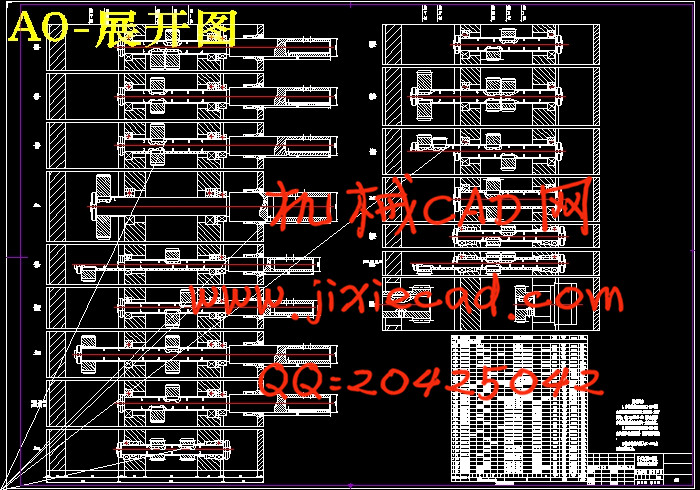
4.3 多轴箱传动设计 21
4.3.1 拟定传动路线 21
4.3.2 确定驱动轴、主轴坐标尺寸 22
4.3.3 确定传动轴位置及齿轮齿数 23
4.4 绘制多轴箱总图及零件图 28
4.4.1 多轴箱零件设计 28
4.4.2 多轴箱总图设计 29
5.组合机床多箱CAD系统 32
结论 33
致 谢 34
参考文献 35
摘 要
机械制造设备的发展是机械工业最主要的环节,目前,机械加工对精度要求越来越高,机械工厂为了降低加工成本,提高加工质量,致使组合机床在制造业中应用越来越广泛,并已显示出巨大的优势。组合机床主要是保证被加工零件的尺寸精度和位置精度要求,高速高效的完成对缸体的加工。在组合机床的设计中,主轴箱加工工艺是关键。绘制主轴箱设计原始移居图,拟定主轴箱的传动路线,应用最优化方法布置齿轮,确定传动参数,绘制主轴箱装配图、箱体补充加工图,并进行轴、齿轮等零件的强度校核。
组合机床主轴箱的基础环节是绘制主轴箱树形图,主轴箱树形图实际上是借鉴了通用机床主传动系统设计中使用的转速图、结构图经演化而来。由于主轴箱传动系统是一个原动件带动多个从动件,没有变速机构,而传动路线条数却很多,出现许多分支。从图形上看,驱动轴相当于树根,各主轴及油泵轴均为末端件,相当于各条树枝的末梢,因此形象地命名为“树形图”。
关键词:组合机床,主轴箱,“三图一卡”,“树形图”
Horizontal double 28 shaft combination drilling machine left spindle box design
Abstract
Machinery manufacturing equipment is the development of the machinery industry the most main link, at present, mechanical processing to the precision requirement more and more high, machinery factory in order to lower manufacturing costs, improve the machining quality, the combination machine tools in the manufacturing industry is more and more extensive application, and has shown great advantage. Combination machine tools is mainly by the size of the processing components to ensure the precision and location accuracy, high speed and high efficient to the finish of machining. In the design of the combination machine tools, spindle box processing technology is the key. Draw spindle box design original moved to figure, draws up the spindle box transmission line, application optimization methods decorate gear, sure drive parameters and draw the spindle box, box added processing chart assembly drawings, and axle, gears and parts of intensity.
Combination machine tools spindle box foundation link is drawing spindle box tree structures, spindle box tree structures is actually lessons from the general machine main transmission system used in the design of the speed diagram, the structure of the evolution. Due to the spindle box transmission system is a former move a drive more follower, no speed changing institutions, and transmission line number but many article, appear many branches. From graphics, it is equivalent to the roots of the drive shaft, the spindle and oil pump shaft are at the end of a thing, which is equivalent to the various peripheral branches, so the image of the named "tree structures".
Key words: transfer and unit machine , Headstock , a three charts card Trees
目录
1. 绪 论 1
1.1 课题背景及目的 1
1.2 国内外研究状况 5
1.3 论文构成及研究内容 6
2. 加工工艺分析 7
3.多轴箱的基本结构及表达方法 9
3.1 多轴箱的组成 10
3.2 多轴箱总图绘制方法特点 10
3.3 多轴箱通用零件 11
4.多轴箱的设计 12
4.1 绘制多轴箱设计原始依据图 12
4.2 主轴、齿轮的确定及动力计算 16
4.2.1 主轴型式和直径、齿轮模数的确定 16
4.2.2 多轴箱所需动力的计算 16
4.3 多轴箱传动设计 21
4.3.1 拟定传动路线 21
4.3.2 确定驱动轴、主轴坐标尺寸 22
4.3.3 确定传动轴位置及齿轮齿数 23
4.4 绘制多轴箱总图及零件图 28
4.4.1 多轴箱零件设计 28
4.4.2 多轴箱总图设计 29
5.组合机床多箱CAD系统 32
结论 33
致 谢 34
参考文献 35