设计简介
卧式双面28轴组合钻床右主轴箱设计
摘 要
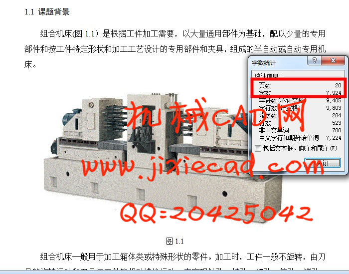
组合机床一般采用多轴、多刀、多工序、多面或多工位同时加工的方式,生产效率比通用机床高几倍至几十倍。由于通用部件已经标准化和系列化,可根据需要灵活配置,能缩短设计和制造周期。组合机床最适宜于加工各种大中型箱体类零件,如汽缸盖、汽缸体、变速箱体、电机座等。
本文主要围绕组合钻床主轴箱的设计来写,分别介绍了课题研究背景及目的、组合机床发展过程概述、论文构成及研究内容,依次说明了加工工艺分析、主轴箱的基本结构及表达方法、主轴箱的设计等内容。
本次设计重点放在主轴箱的结构设计上,同时介绍齿轮位置的设计和齿轮轴以及其它部件的选用。另外还包括设计多轴箱总图,包括绘制主视图、展开图、编制装配表,绘制技术条件等四部分。
关键词:组合机床,钻床,主轴箱,主轴
Horizontal double sided 28shaft combination drilling machine right headstock design
Abstract
.Combination machine generally adopts multi shaft, knife, more processes, more or multiple locations simultaneously processes, and production efficiency ratio general machine tool high several times to several times. As generic components have been standardized and serialized, may need to be flexible configuration, can shorten design and manufacturing cycle. Combination machine is most suitable for processing a variety of large and medium-sized box-type parts, such as cylinder cap, a cylinder body, a gear box, motor seat.
This paper mainly focus on the combination drilling machine spindle box designed to write, which introduces the research background and purpose, combined machine tool development process overview, composition and content of the paper, which explains the process analysis of the spindle box, the basic structure and expression method, the design of spindle box etc..
The design focus on the structure of the spindle box design, and introduces the design of gear position and gear shaft and other components. Also includes the design of spindle assembly drawing, including drawing the main view, unfolded drawing, drawing the assembly table, drawing the technical conditions of part four.
Key words: Combination machine, drilling machine, spindle box, spindle
目 录
1.绪论 1
1.1 课题背景 2
1.2 国内外研究状况 3
1.3 论文构成及研究内容 4
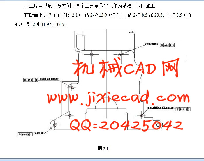
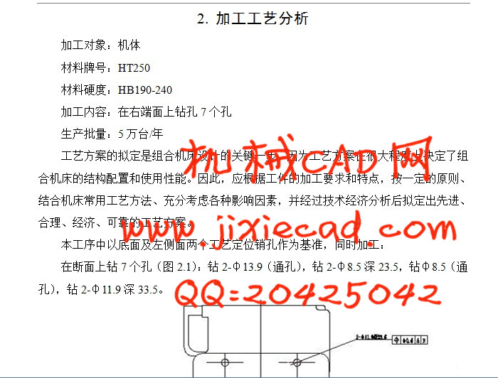
2. 加工工艺分析 6
3.多轴箱的基本结构及表达方法 6
3.1 多轴箱的组成 6
3.2 多轴箱总图绘制方法特点 6
3.3 多轴箱通用零件 6
4.多轴箱的设计 8
4.1 绘制多轴箱设计原始依据图 8
4.2 主轴、齿轮的确定及动力计算 10
4.2.1 主轴型式和直径、齿轮模数的确定 10
4.2.2 多轴箱所需动力的计算 10
4.3 多轴箱传动设计 12
4.3.1 拟定传动路线 12
4.3.2 确定驱动轴、主轴坐标尺寸 13
4.3.3 确定传动轴位置及齿轮齿数 13
4.4 绘制多轴箱总图及零件图 16
4.4.1 多轴箱零件设计 16
4.4.2 多轴箱总图设计 16
结 论 18
致 谢 19
参考文献 20
摘 要
组合机床一般采用多轴、多刀、多工序、多面或多工位同时加工的方式,生产效率比通用机床高几倍至几十倍。由于通用部件已经标准化和系列化,可根据需要灵活配置,能缩短设计和制造周期。组合机床最适宜于加工各种大中型箱体类零件,如汽缸盖、汽缸体、变速箱体、电机座等。
本文主要围绕组合钻床主轴箱的设计来写,分别介绍了课题研究背景及目的、组合机床发展过程概述、论文构成及研究内容,依次说明了加工工艺分析、主轴箱的基本结构及表达方法、主轴箱的设计等内容。
本次设计重点放在主轴箱的结构设计上,同时介绍齿轮位置的设计和齿轮轴以及其它部件的选用。另外还包括设计多轴箱总图,包括绘制主视图、展开图、编制装配表,绘制技术条件等四部分。
关键词:组合机床,钻床,主轴箱,主轴
Horizontal double sided 28shaft combination drilling machine right headstock design
Abstract
.Combination machine generally adopts multi shaft, knife, more processes, more or multiple locations simultaneously processes, and production efficiency ratio general machine tool high several times to several times. As generic components have been standardized and serialized, may need to be flexible configuration, can shorten design and manufacturing cycle. Combination machine is most suitable for processing a variety of large and medium-sized box-type parts, such as cylinder cap, a cylinder body, a gear box, motor seat.
This paper mainly focus on the combination drilling machine spindle box designed to write, which introduces the research background and purpose, combined machine tool development process overview, composition and content of the paper, which explains the process analysis of the spindle box, the basic structure and expression method, the design of spindle box etc..
The design focus on the structure of the spindle box design, and introduces the design of gear position and gear shaft and other components. Also includes the design of spindle assembly drawing, including drawing the main view, unfolded drawing, drawing the assembly table, drawing the technical conditions of part four.
Key words: Combination machine, drilling machine, spindle box, spindle
目 录
1.绪论 1
1.1 课题背景 2
1.2 国内外研究状况 3
1.3 论文构成及研究内容 4
2. 加工工艺分析 6
3.多轴箱的基本结构及表达方法 6
3.1 多轴箱的组成 6
3.2 多轴箱总图绘制方法特点 6
3.3 多轴箱通用零件 6
4.多轴箱的设计 8
4.1 绘制多轴箱设计原始依据图 8
4.2 主轴、齿轮的确定及动力计算 10
4.2.1 主轴型式和直径、齿轮模数的确定 10
4.2.2 多轴箱所需动力的计算 10
4.3 多轴箱传动设计 12
4.3.1 拟定传动路线 12
4.3.2 确定驱动轴、主轴坐标尺寸 13
4.3.3 确定传动轴位置及齿轮齿数 13
4.4 绘制多轴箱总图及零件图 16
4.4.1 多轴箱零件设计 16
4.4.2 多轴箱总图设计 16
结 论 18
致 谢 19
参考文献 20