设计简介
摘 要
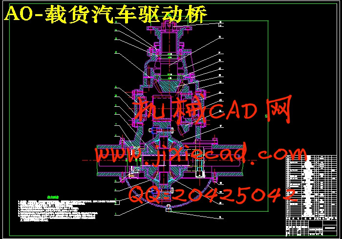
驱动桥作为汽车的重要组成部分,它的性能的好坏直接影响整车性能。其一般由主减速器、差速器、半轴及桥壳四部分组成,基本功用是增大由传动轴或直接由变速器传来的转矩,将转矩分配给左、右车轮,并使左、右驱动车轮具有汽车行驶运动学所要求的差速功能;此外,还要承受作用于路面和车架或车厢之间的铅垂力、纵向力和横向力。此次设计先论述了驱动桥的总体结构,在分析驱动桥各部分结构型式、发展过程及其以往形式的优缺点的基础上,确定了总体设计方案:采用整体式驱动桥,主减速器的减速型式采用双级减速器,主减速器齿轮采用螺旋锥齿轮,差速器采用圆锥行星齿轮差速器,半轴采用全浮式型式,桥壳采用铸造整体式桥壳。此次设计中,主要完成了双级减速器、圆锥行星齿轮差速器、全浮式半轴的设计和桥壳的校核及材料选取等工作。
关键字:驱动桥、双级主减速器、弧齿锥齿轮、
ABSTRACT
Driving axle assembly is one of the important vehicle carrying pieces and can directly impact on the whole vehicle's performance and its effective life. Driving Axle is consisted of Main Decelerator, Differential Mechanism, Half Shaft and Axle Housing. The basic function of Driving Axle is to increase the torque transmitted by Drive Shaft or directly transmitted by Gearbox, then distributes it to left and right wheel, and make these two wheels have the differential function which is required in Automobile Driving Kinematics; besides, the Driving Axle must also stand the lead hangs down strength, the longitudinal force and the transverse force acted on the road surface, the frame or the compartment lead.The configuration of the Driving Axle is introduced in the thesis at first. On the basis of the analysis of the structure and the developing process of Driving Axle, the design adopted the Integral Driving Axle, Double Reduction Gear for Main Decelerator’s deceleration form, Spiral Bevel Gear for Main Decelerator’s gear, Full Floating for Axle and Casting Integral Axle Housing for Axle Housing. In the design, we accomplished the design for Double Reduction Gear, tapered Planetary Gear Differential Mechanism, Full Floating Axle, the checking of Axle Housing and the election of the material and so on.
Key words: Driving Axle;Double Main Decelerator;Single Reduction Final Drive
目 录
摘 要 I
ABSTRACT II
目 录 III
第1章 绪论 1
1.1选题的目的和意义 1
1.2研究现状 1
1.2.1国内现状 1
1.2.2国外现状 2
第2章 驱动桥结构方案分析 4
第3章 主减速器设计 5
3.1 主减速器的结构形式 5
3.1.1 主减速器的齿轮类型 5
3.1.2 主减速器的减速形式 5
3.1.3 主减速器主,从动锥齿轮的支承形式 5
3.2 主减速器的基本参数选择与设计计算 6
3.2.1 主减速器计算载荷的确定 6
3.2.2 主减速器基本参数的选择 8
3.2.3主减速器圆弧锥齿轮的几何尺寸计算 10
3.2.4 主减速器圆弧锥齿轮的强度计算 10
3.2.5 主减速器齿轮的材料及热处理 14
3.2.6 主减速器轴承的计算 15
第4章 差速器设计 22
4.1 对称式圆锥行星齿轮差速器的差速原理 22
4.2 对称式圆锥行星齿轮差速器的结构 23
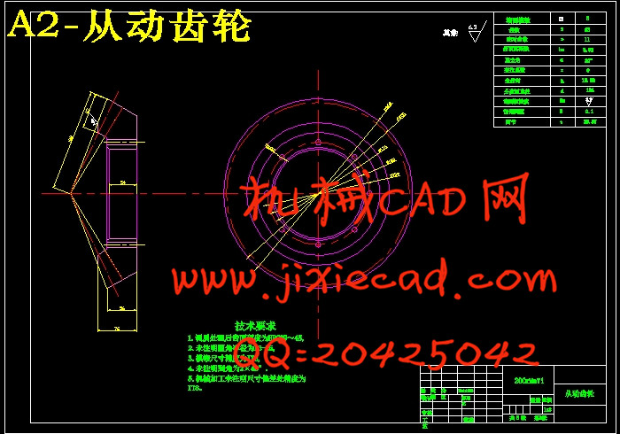
4.3 对称式圆锥行星齿轮差速器的设计 24
4.3.1 差速器齿轮的基本参数的选择 24
4.3.2 差速器齿轮的几何计算 26
4.3.3 差速器齿轮的强度计算 26
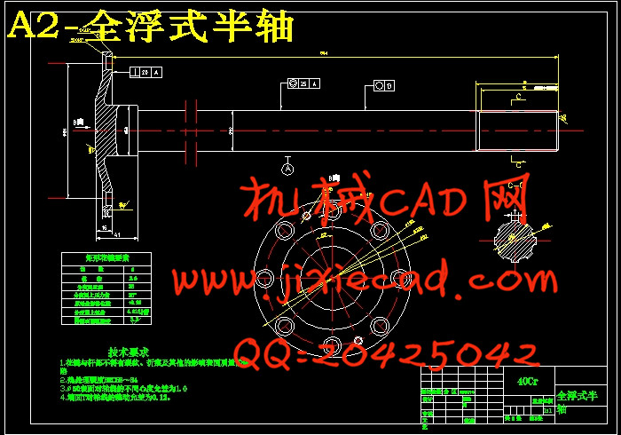
第5章 驱动半轴的设计 28
5.1 全浮式半轴计算载荷的确定 28
5.2 全浮式半轴的杆部直径的初选 29
5.3 全浮式半轴的强度计算 29
5.4 半轴花键的强度计算 30
第6章 驱动桥壳的设计 31
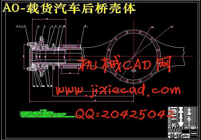
6.1 铸造整体式桥壳的结构 31
6.2 桥壳的受力分析与强度计算 32
6.2.1 桥壳的静弯曲应力计算 32
6.2.2 在不平路面冲击载荷作用下的桥壳强度计算 35
6.2.3 汽车以最大牵引力行驶时的桥壳强度计算 35
结 论 38
致 谢 39
参考文献 40
附 录 41
驱动桥作为汽车的重要组成部分,它的性能的好坏直接影响整车性能。其一般由主减速器、差速器、半轴及桥壳四部分组成,基本功用是增大由传动轴或直接由变速器传来的转矩,将转矩分配给左、右车轮,并使左、右驱动车轮具有汽车行驶运动学所要求的差速功能;此外,还要承受作用于路面和车架或车厢之间的铅垂力、纵向力和横向力。此次设计先论述了驱动桥的总体结构,在分析驱动桥各部分结构型式、发展过程及其以往形式的优缺点的基础上,确定了总体设计方案:采用整体式驱动桥,主减速器的减速型式采用双级减速器,主减速器齿轮采用螺旋锥齿轮,差速器采用圆锥行星齿轮差速器,半轴采用全浮式型式,桥壳采用铸造整体式桥壳。此次设计中,主要完成了双级减速器、圆锥行星齿轮差速器、全浮式半轴的设计和桥壳的校核及材料选取等工作。
关键字:驱动桥、双级主减速器、弧齿锥齿轮、
ABSTRACT
Driving axle assembly is one of the important vehicle carrying pieces and can directly impact on the whole vehicle's performance and its effective life. Driving Axle is consisted of Main Decelerator, Differential Mechanism, Half Shaft and Axle Housing. The basic function of Driving Axle is to increase the torque transmitted by Drive Shaft or directly transmitted by Gearbox, then distributes it to left and right wheel, and make these two wheels have the differential function which is required in Automobile Driving Kinematics; besides, the Driving Axle must also stand the lead hangs down strength, the longitudinal force and the transverse force acted on the road surface, the frame or the compartment lead.The configuration of the Driving Axle is introduced in the thesis at first. On the basis of the analysis of the structure and the developing process of Driving Axle, the design adopted the Integral Driving Axle, Double Reduction Gear for Main Decelerator’s deceleration form, Spiral Bevel Gear for Main Decelerator’s gear, Full Floating for Axle and Casting Integral Axle Housing for Axle Housing. In the design, we accomplished the design for Double Reduction Gear, tapered Planetary Gear Differential Mechanism, Full Floating Axle, the checking of Axle Housing and the election of the material and so on.
Key words: Driving Axle;Double Main Decelerator;Single Reduction Final Drive
目 录
摘 要 I
ABSTRACT II
目 录 III
第1章 绪论 1
1.1选题的目的和意义 1
1.2研究现状 1
1.2.1国内现状 1
1.2.2国外现状 2
第2章 驱动桥结构方案分析 4
第3章 主减速器设计 5
3.1 主减速器的结构形式 5
3.1.1 主减速器的齿轮类型 5
3.1.2 主减速器的减速形式 5
3.1.3 主减速器主,从动锥齿轮的支承形式 5
3.2 主减速器的基本参数选择与设计计算 6
3.2.1 主减速器计算载荷的确定 6
3.2.2 主减速器基本参数的选择 8
3.2.3主减速器圆弧锥齿轮的几何尺寸计算 10
3.2.4 主减速器圆弧锥齿轮的强度计算 10
3.2.5 主减速器齿轮的材料及热处理 14
3.2.6 主减速器轴承的计算 15
第4章 差速器设计 22
4.1 对称式圆锥行星齿轮差速器的差速原理 22
4.2 对称式圆锥行星齿轮差速器的结构 23
4.3 对称式圆锥行星齿轮差速器的设计 24
4.3.1 差速器齿轮的基本参数的选择 24
4.3.2 差速器齿轮的几何计算 26
4.3.3 差速器齿轮的强度计算 26
第5章 驱动半轴的设计 28
5.1 全浮式半轴计算载荷的确定 28
5.2 全浮式半轴的杆部直径的初选 29
5.3 全浮式半轴的强度计算 29
5.4 半轴花键的强度计算 30
第6章 驱动桥壳的设计 31
6.1 铸造整体式桥壳的结构 31
6.2 桥壳的受力分析与强度计算 32
6.2.1 桥壳的静弯曲应力计算 32
6.2.2 在不平路面冲击载荷作用下的桥壳强度计算 35
6.2.3 汽车以最大牵引力行驶时的桥壳强度计算 35
结 论 38
致 谢 39
参考文献 40
附 录 41