设计简介
木工用异型槽龙门铣床除尘及液压系统改进设计
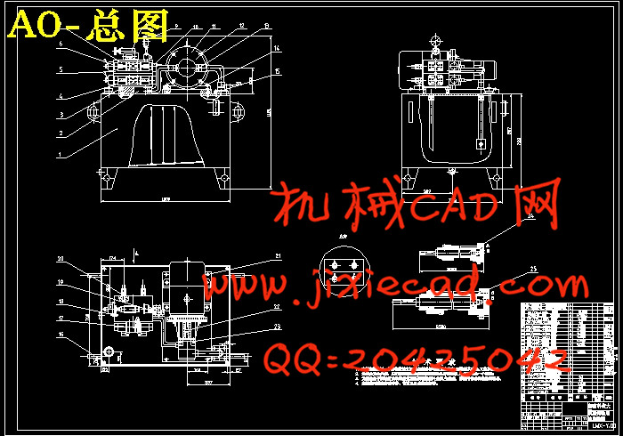
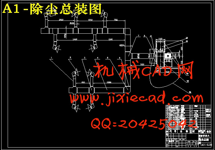
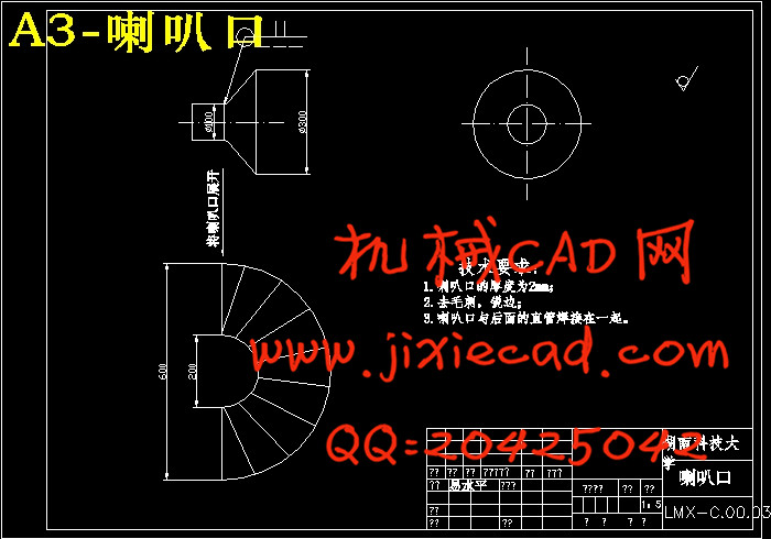
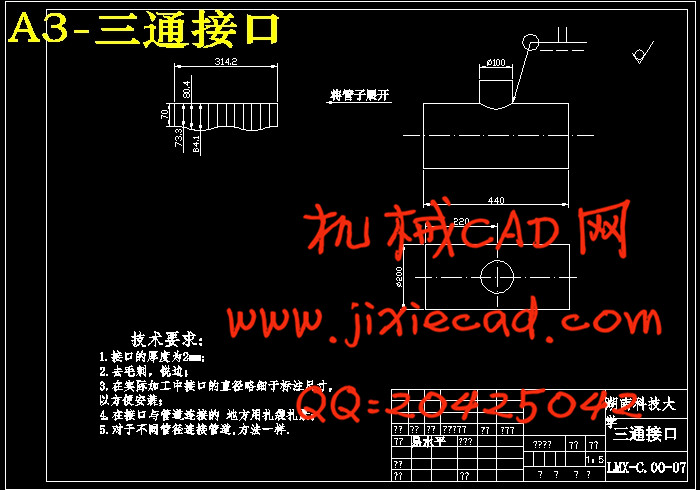
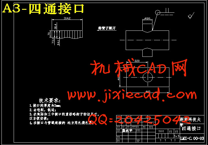
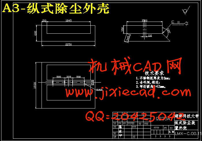
摘 要:为了快速方便地驱动木工用异型槽龙门铣床工作台使其往复直线运动。专门设计纵、横式机床合用的液压系统。通过液压泵把驱动液压泵的电动机的机械能转换成油液的压力能,经过各种控制阀送到作为执行器的液压缸中,再转换成机械动力去驱动负载。设计过程中根据工作台的重量,行程等加工参数确定液压系统的总体方案。选择了压力控制阀、流量控制阀、方向控制阀、管接头等元器件;设计了油箱隔板、滤气网等系列器件。在管路上,采用的是精密无缝钢管;液压箱为自行设计。本系统操作灵活方便,自动化程度高;性能可靠,功能完善。在除尘设计当中采用离心鼓风机作为除尘装置的动力源。整个装置经由安装在刀具上的喇叭口将机床加工过程中产生的木屑吸入分管道,最后汇总进入总管道接入风机,由风机的出风口处将木屑排入布袋中。在这里,只使用一个风机控制机床的横式和纵式机床部分。此外,还有一个防护罩安装横梁上以防止木屑飞溅出来,对工人的操作有所影响。这个装置的特点是结构简单,使用方便,价格低廉。
关键词:铣床;液压;性能;除尘;风机;防护罩。
The dusted and improved on hydraulic system design of gantry milling machine for special-shaped groove woodworking
Abstract: In order to actuates the workbench moving conveniently, the hydraulic system which can be used both in horizontal and vertical type is designed. Through the hydraulic pump, the hydraulic can actuates the mechanical energy of the electric motor to transform the pressure deliver energy of oil it to the liguor, pass through all kinds of control valve, hydraulic cylinder which is used as execution valve and transform the mechanical power to actuate the load again. In the design process acts according to the weight, processing parameter of workbench hydraulic system overall plan determined. The pressure control valve, the flow control valve, the direction control valve, and the pipe joint primary device are chosed. The fuel tank partition board, the filter purify air net and so on by the series component are designed. On the pipeline, the precise seamless steel pipe is used , the hydraulic tank is designed independently. This system operation is convenient, the automaticlity is high; the performance is reliable, the function is perfect. It is adopted the acentric fans as the drive in the design of dusting. The dust produced in the process of machining is soaked into the bell-mouthed which is fixed in the cutler to the pipeline, at last gathered in the pipeline which is bowed in fans, and pass through the exit of fans to the hop-pocket. This, only using one fans to control all of the two structures that included horizontal and vertical. There is a shield fixed up in the beam as to the dust splash and affect the worker. The excellence of this device are simple structure, advantageous using , lowed price.
Key words: Milling machine;Hydraulic pressure;Performance;Fans;Dust catcher;Shield.
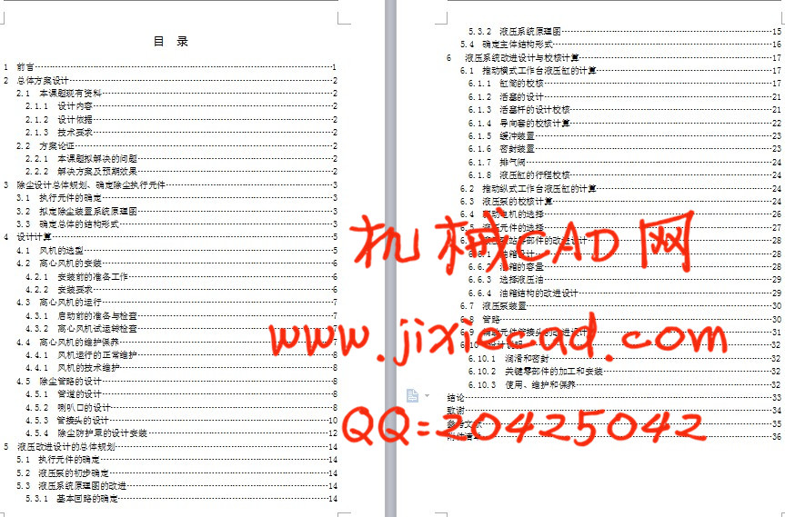
目 录
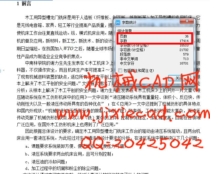
1 前言…………………………………………………………………………………………1
2 总体方案设计………………………………………………………………………………2
2.1 本课题现有资料……………………………………………………………………2
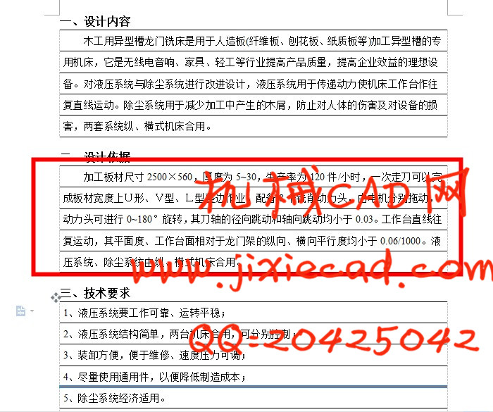
2.1.1 设计内容………………………………………………………………………2
2.1.2 设计依据………………………………………………………………………2
2.1.3 技术要求………………………………………………………………………2
2.2 方案论证……………………………………………………………………………2
2.2.1 本课题拟解决的问题…………………………………………………………2
2.2.2 解决方案及预期效果…………………………………………………………2
3 除尘设计总体规划、确定除尘执行元件…………………………………………………3
3.1 执行元件的确定……………………………………………………………………3
3.2 拟定除尘装置系统原理图…………………………………………………………3
3.3 确定总体的结构形式………………………………………………………………3
4 设计计算……………………………………………………………………………………5
4.1 风机的选型…………………………………………………………………………5
4.2 离心风机的安装……………………………………………………………………6
4.2.1 安装前的准备工作……………………………………………………………6
4.2.2 安装要求………………………………………………………………………6
4.3 离心风机的运行……………………………………………………………………7
4.3.1 启动前的准备与检查…………………………………………………………7
4.3.2 离心风机试运转检查…………………………………………………………7
4.4 离心风机的维护保养………………………………………………………………7
4.4.1 风机运行的正常维护…………………………………………………………8
4.4.1 风机的技术维护………………………………………………………………8
4.5 除尘管路的设计……………………………………………………………………8
4.5.1 管道的设计……………………………………………………………………8
4.5.2 喇叭口的设计…………………………………………………………………8
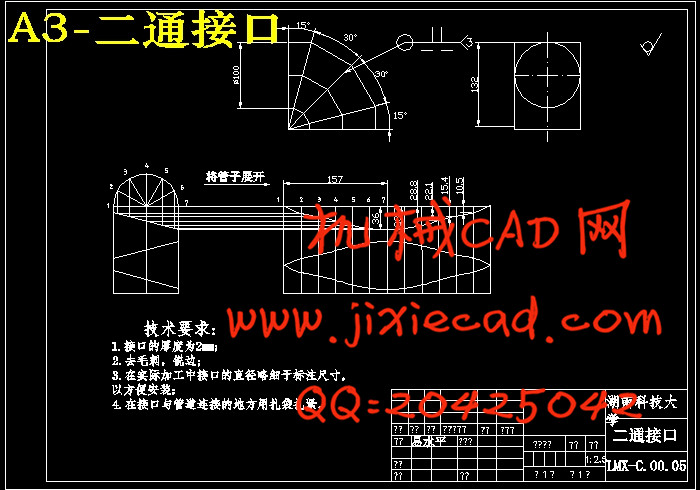
4.5.3 管接头的设计…………………………………………………………………10
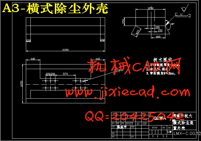
4.5.4 除尘防护罩的设计安装……………………………………………………12
5 液压改进设计的总体规划………………………………………………………………14
5.1 执行元件的确定……………………………………………………………………14
5.2 液压泵的初步确定…………………………………………………………………14
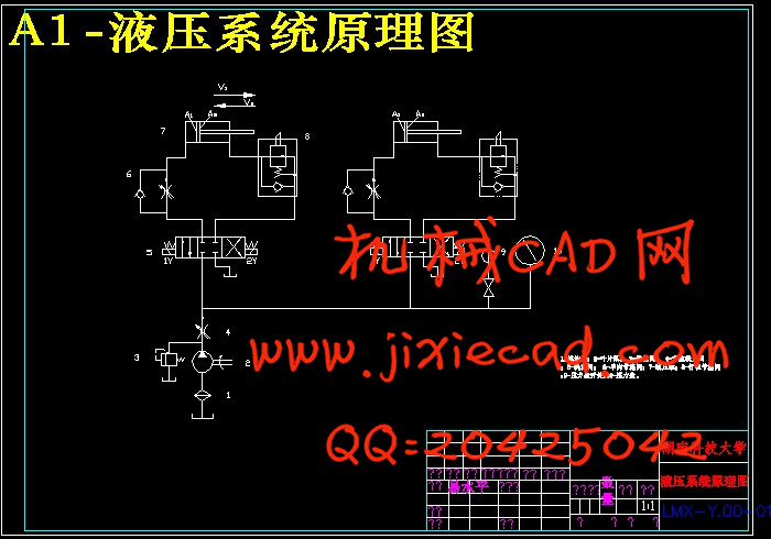
5.3 液压系统原理图的改进……………………………………………………………14
5.3.1 基本回路的确定………………………………………………………………14
5.3.2 液压系统原理图………………………………………………………………15
5.4 确定主体结构形式…………………………………………………………………16
6 液压系统改进设计与校核计算…………………………………………………………17
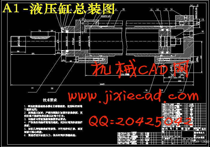
6.1 推动横式工作台液压缸的计算……………………………………………………17
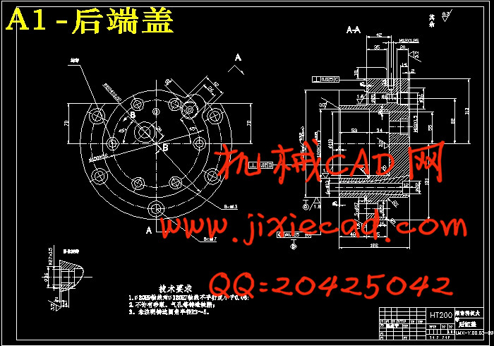
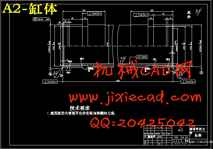
6.1.1 缸筒的校核……………………………………………………………………17
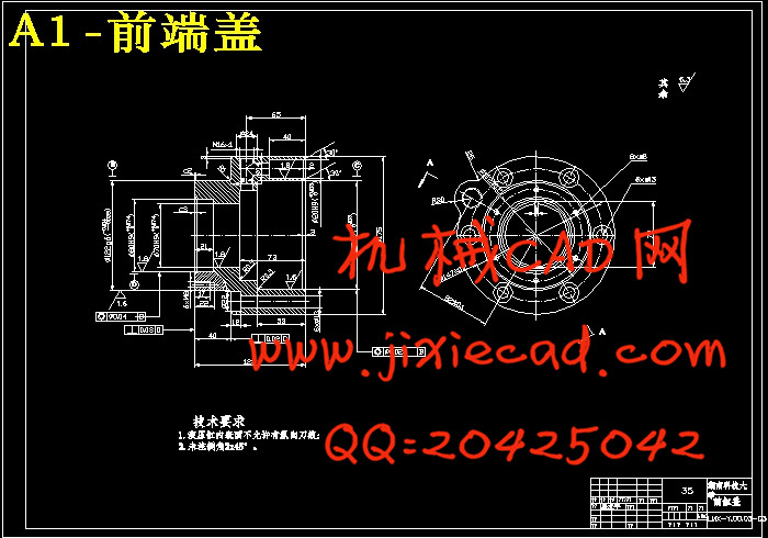
6.1.2 活塞的设计……………………………………………………………………21
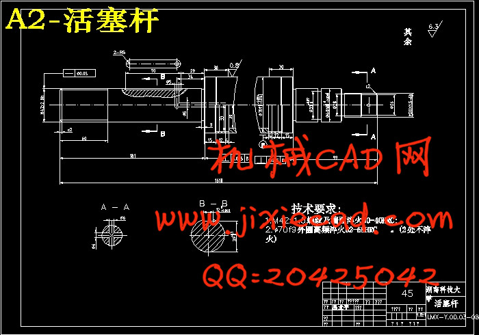
6.1.3 活塞杆的设计校核……………………………………………………………21
6.1.4 导向套的校核计算……………………………………………………………22
6.1.5 缓冲装置………………………………………………………………………23
6.1.6 密封装置………………………………………………………………………23
6.1.7 排气阀…………………………………………………………………………24
6.1.8 液压缸的行程校核……………………………………………………………24
6.2 推动纵式工作台液压缸的计算……………………………………………………24
6.3 液压泵的校核计算…………………………………………………………………24
6.4 驱动电机的选择……………………………………………………………………26
6.5 液压元件的选择……………………………………………………………………27
6.6 液压泵站零部件的改进设计………………………………………………………28
6.6.1 油箱设计………………………………………………………………………28
6.6.2 油箱的容量……………………………………………………………………28
6.6.3 选择液压油……………………………………………………………………29
6.6.4 油箱结构的改进设计…………………………………………………………29
6.7 液压泵装置…………………………………………………………………………30
6.8 管路…………………………………………………………………………………30
6.9 辅助元件管接头的改进设计………………………………………………………31
6.10 设计说明…………………………………………………………………………32
6.10.1 润滑和密封…………………………………………………………………32
6.10.2 关键零部件的加工和安装…………………………………………………32
6.10.3 使用、维护和保养…………………………………………………………32
结论……………………………………………………………………………………………33
致谢……………………………………………………………………………………………34
参考文献………………………………………………………………………………………35
摘 要:为了快速方便地驱动木工用异型槽龙门铣床工作台使其往复直线运动。专门设计纵、横式机床合用的液压系统。通过液压泵把驱动液压泵的电动机的机械能转换成油液的压力能,经过各种控制阀送到作为执行器的液压缸中,再转换成机械动力去驱动负载。设计过程中根据工作台的重量,行程等加工参数确定液压系统的总体方案。选择了压力控制阀、流量控制阀、方向控制阀、管接头等元器件;设计了油箱隔板、滤气网等系列器件。在管路上,采用的是精密无缝钢管;液压箱为自行设计。本系统操作灵活方便,自动化程度高;性能可靠,功能完善。在除尘设计当中采用离心鼓风机作为除尘装置的动力源。整个装置经由安装在刀具上的喇叭口将机床加工过程中产生的木屑吸入分管道,最后汇总进入总管道接入风机,由风机的出风口处将木屑排入布袋中。在这里,只使用一个风机控制机床的横式和纵式机床部分。此外,还有一个防护罩安装横梁上以防止木屑飞溅出来,对工人的操作有所影响。这个装置的特点是结构简单,使用方便,价格低廉。
关键词:铣床;液压;性能;除尘;风机;防护罩。
The dusted and improved on hydraulic system design of gantry milling machine for special-shaped groove woodworking
Abstract: In order to actuates the workbench moving conveniently, the hydraulic system which can be used both in horizontal and vertical type is designed. Through the hydraulic pump, the hydraulic can actuates the mechanical energy of the electric motor to transform the pressure deliver energy of oil it to the liguor, pass through all kinds of control valve, hydraulic cylinder which is used as execution valve and transform the mechanical power to actuate the load again. In the design process acts according to the weight, processing parameter of workbench hydraulic system overall plan determined. The pressure control valve, the flow control valve, the direction control valve, and the pipe joint primary device are chosed. The fuel tank partition board, the filter purify air net and so on by the series component are designed. On the pipeline, the precise seamless steel pipe is used , the hydraulic tank is designed independently. This system operation is convenient, the automaticlity is high; the performance is reliable, the function is perfect. It is adopted the acentric fans as the drive in the design of dusting. The dust produced in the process of machining is soaked into the bell-mouthed which is fixed in the cutler to the pipeline, at last gathered in the pipeline which is bowed in fans, and pass through the exit of fans to the hop-pocket. This, only using one fans to control all of the two structures that included horizontal and vertical. There is a shield fixed up in the beam as to the dust splash and affect the worker. The excellence of this device are simple structure, advantageous using , lowed price.
Key words: Milling machine;Hydraulic pressure;Performance;Fans;Dust catcher;Shield.
目 录
1 前言…………………………………………………………………………………………1
2 总体方案设计………………………………………………………………………………2
2.1 本课题现有资料……………………………………………………………………2
2.1.1 设计内容………………………………………………………………………2
2.1.2 设计依据………………………………………………………………………2
2.1.3 技术要求………………………………………………………………………2
2.2 方案论证……………………………………………………………………………2
2.2.1 本课题拟解决的问题…………………………………………………………2
2.2.2 解决方案及预期效果…………………………………………………………2
3 除尘设计总体规划、确定除尘执行元件…………………………………………………3
3.1 执行元件的确定……………………………………………………………………3
3.2 拟定除尘装置系统原理图…………………………………………………………3
3.3 确定总体的结构形式………………………………………………………………3
4 设计计算……………………………………………………………………………………5
4.1 风机的选型…………………………………………………………………………5
4.2 离心风机的安装……………………………………………………………………6
4.2.1 安装前的准备工作……………………………………………………………6
4.2.2 安装要求………………………………………………………………………6
4.3 离心风机的运行……………………………………………………………………7
4.3.1 启动前的准备与检查…………………………………………………………7
4.3.2 离心风机试运转检查…………………………………………………………7
4.4 离心风机的维护保养………………………………………………………………7
4.4.1 风机运行的正常维护…………………………………………………………8
4.4.1 风机的技术维护………………………………………………………………8
4.5 除尘管路的设计……………………………………………………………………8
4.5.1 管道的设计……………………………………………………………………8
4.5.2 喇叭口的设计…………………………………………………………………8
4.5.3 管接头的设计…………………………………………………………………10
4.5.4 除尘防护罩的设计安装……………………………………………………12
5 液压改进设计的总体规划………………………………………………………………14
5.1 执行元件的确定……………………………………………………………………14
5.2 液压泵的初步确定…………………………………………………………………14
5.3 液压系统原理图的改进……………………………………………………………14
5.3.1 基本回路的确定………………………………………………………………14
5.3.2 液压系统原理图………………………………………………………………15
5.4 确定主体结构形式…………………………………………………………………16
6 液压系统改进设计与校核计算…………………………………………………………17
6.1 推动横式工作台液压缸的计算……………………………………………………17
6.1.1 缸筒的校核……………………………………………………………………17
6.1.2 活塞的设计……………………………………………………………………21
6.1.3 活塞杆的设计校核……………………………………………………………21
6.1.4 导向套的校核计算……………………………………………………………22
6.1.5 缓冲装置………………………………………………………………………23
6.1.6 密封装置………………………………………………………………………23
6.1.7 排气阀…………………………………………………………………………24
6.1.8 液压缸的行程校核……………………………………………………………24
6.2 推动纵式工作台液压缸的计算……………………………………………………24
6.3 液压泵的校核计算…………………………………………………………………24
6.4 驱动电机的选择……………………………………………………………………26
6.5 液压元件的选择……………………………………………………………………27
6.6 液压泵站零部件的改进设计………………………………………………………28
6.6.1 油箱设计………………………………………………………………………28
6.6.2 油箱的容量……………………………………………………………………28
6.6.3 选择液压油……………………………………………………………………29
6.6.4 油箱结构的改进设计…………………………………………………………29
6.7 液压泵装置…………………………………………………………………………30
6.8 管路…………………………………………………………………………………30
6.9 辅助元件管接头的改进设计………………………………………………………31
6.10 设计说明…………………………………………………………………………32
6.10.1 润滑和密封…………………………………………………………………32
6.10.2 关键零部件的加工和安装…………………………………………………32
6.10.3 使用、维护和保养…………………………………………………………32
结论……………………………………………………………………………………………33
致谢……………………………………………………………………………………………34
参考文献………………………………………………………………………………………35