设计简介
摘 要
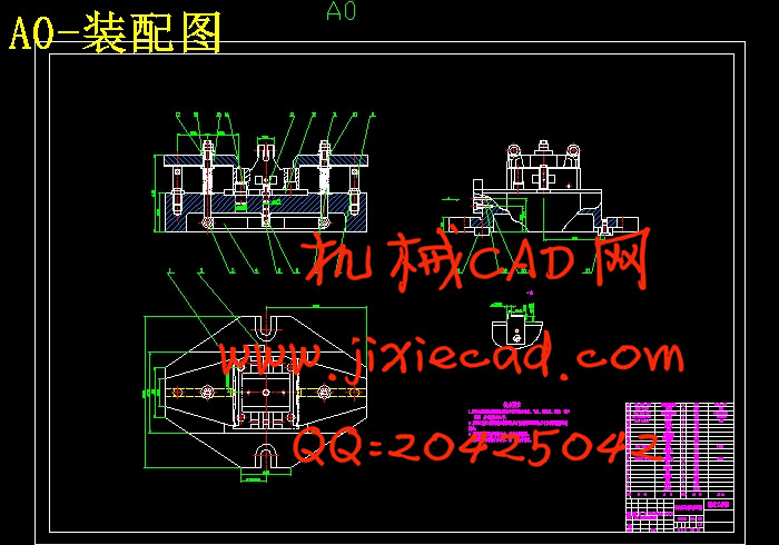
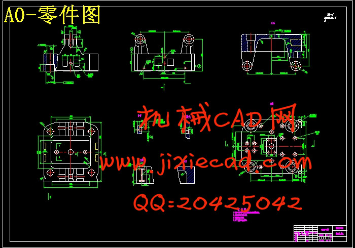
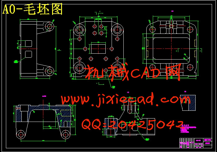
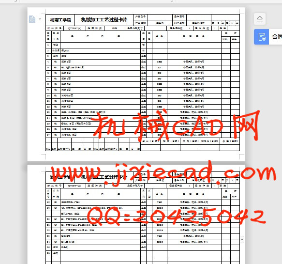
本设计课题是“注塑机尾板机械加工工艺规程及夹具设计”。该尾板是注塑机最主要的部件之一,它与注塑机的四根拉杆配合,可沿拉杆方向滑动。主要作用一是安装液压缸,二是连接拉杆,形成合模力。本设计旨在对该零件进行加工工艺方案的设计及其相对应的专用夹具的设计,以保证该零件的加工质量并提高生产效率。由此我们首先对尾板的结构和技术要求进行了仔细的分析,然后参考相应资料,确定了一套较合理的机械加工工艺方案,并且确定了各工序的加工余量、工序尺寸、公差及切削用量等参数,完成了工序过程卡、工序卡。然后,为了提高劳动生产率,降低劳动强度,保证加工质量,要设计一些专用夹具,为此选择了第14道铣支耳外侧面工序进行夹具设计,确定了夹具的定位、夹紧方案,进行了夹紧力和夹具的误差分析,并绘制了夹具装配图。
关键词 注塑机尾板;加工工艺;夹具;设计
ABSTRACT
The topic of my graduation design is "The machining process procedures and Fixture design of the Injection tail board " . The tail board is the most import part of Injection machine that cooperate with four bars , and can glide by the direction of the bars . The main function are installing hydraulic cylinder and connecting bars to form mold clamping force . This project is aim at designing the processing technic scheme of components and the corresponding fixtures used in special purpose to improve the production efficiency . First of all , I should make a analysis about the structure of tail board and technical requirements carefully , then refer to the relevant materials to determine a set of reasonable machining process procedures and parameters , such as : machining allowance、size、tolerance、cutting date of each process . Finished the process cards . In order to improve the labour productivity、reduce the intensity involved in the labour、ensure the processing quality , I should design some special fixtures .so that I choose the 14th course process of milling journal stirrup outside part to make the fixture design and make a analysis of clamp force and fixtures ' error、ensure the location of fixture , and the clamp scheme . Finally, assembly drawing of the fixtures .
Key words injection tail board; processing technology; fixture; design
目 录本设计课题是“注塑机尾板机械加工工艺规程及夹具设计”。该尾板是注塑机最主要的部件之一,它与注塑机的四根拉杆配合,可沿拉杆方向滑动。主要作用一是安装液压缸,二是连接拉杆,形成合模力。本设计旨在对该零件进行加工工艺方案的设计及其相对应的专用夹具的设计,以保证该零件的加工质量并提高生产效率。由此我们首先对尾板的结构和技术要求进行了仔细的分析,然后参考相应资料,确定了一套较合理的机械加工工艺方案,并且确定了各工序的加工余量、工序尺寸、公差及切削用量等参数,完成了工序过程卡、工序卡。然后,为了提高劳动生产率,降低劳动强度,保证加工质量,要设计一些专用夹具,为此选择了第14道铣支耳外侧面工序进行夹具设计,确定了夹具的定位、夹紧方案,进行了夹紧力和夹具的误差分析,并绘制了夹具装配图。
关键词 注塑机尾板;加工工艺;夹具;设计
ABSTRACT
The topic of my graduation design is "The machining process procedures and Fixture design of the Injection tail board " . The tail board is the most import part of Injection machine that cooperate with four bars , and can glide by the direction of the bars . The main function are installing hydraulic cylinder and connecting bars to form mold clamping force . This project is aim at designing the processing technic scheme of components and the corresponding fixtures used in special purpose to improve the production efficiency . First of all , I should make a analysis about the structure of tail board and technical requirements carefully , then refer to the relevant materials to determine a set of reasonable machining process procedures and parameters , such as : machining allowance、size、tolerance、cutting date of each process . Finished the process cards . In order to improve the labour productivity、reduce the intensity involved in the labour、ensure the processing quality , I should design some special fixtures .so that I choose the 14th course process of milling journal stirrup outside part to make the fixture design and make a analysis of clamp force and fixtures ' error、ensure the location of fixture , and the clamp scheme . Finally, assembly drawing of the fixtures .
Key words injection tail board; processing technology; fixture; design
1 零件的分析 1
1.1 零件的作用 1
1.2 零件的工艺分析 1
2 确定毛坯的制造形式 2
3 工艺规程的设计 2
3.1 定位基准的选择 2
3.1.1 粗基准的选择 2
3.1.2 精基准的选择 2
3.2 零件表面加工方法的选择 2
3.3 制订工艺路线 3
3.4 加工设备及工艺装备的选择 4
3.4.1 粗铣和精铣A面 4
3.4.2 钻、扩中心孔Ф55 5
3.4.3 粗铣和半精铣B面 5
3.4.4 粗铣和精铣F面 6
3.4.5 粗铣和半精铣C面 6
3.4.6 粗镗,半精镗4-Ф65,4-Ф90 6
3.4.7 粗铣,半精铣支耳外侧面(D,E面) 7
3.4.8 粗铣,半精铣支耳内侧面(G,H面) 7
3.4.9 镗支耳孔4-Ф60 7
3.4.10 钻、扩螺纹孔12-M16深35、4-M12深25、2-M10深12,钻、铰2- Ф13.5及锪孔2- Ф40 8
3.4.11 钻、扩侧面孔4-M10深10,2-M8深20 8
3.4.12 粗铣油槽 9
3.4.13 钻孔Ф5 9
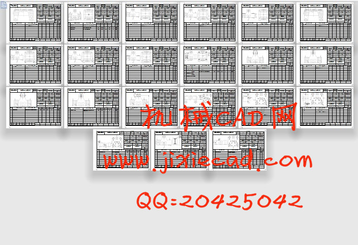
3.5 机械加工余量、工序尺寸及其公差的确定 10
3.6 切削用量及机本工时的确定 14
3.6.1 切削用量的选择原则 14
3.6.2 确定切削用量及基本工时 15
4 夹具设计 26
4.1 问题的提出 26
4.2 夹具的设计 26
4.2.1 定位基准的选择 26
4.2.2 切削力及夹紧力计算 26
4.3 校核机床功率 27
4.4 定位误差分析 28
4.5 夹具设计操作及简要设计说明 28
参考文献 29
致 谢 30