设计简介
摘 要
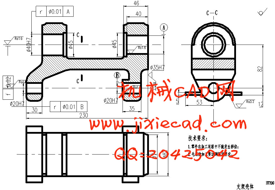
本课题的主要研究内容是某种壳体零件的机械加工工艺及其夹具设计。壳体零件是一种很重要的零件,它起到了支承和包容传动的作用。本课题的主要任务就是设计一种加工成本低,加工时间短,加工过程合理的方案,以及设计一种专用夹具。在设计初,首先要看懂零件图,并对零件的结构和工艺进行分析,明确粗基准和精基准的选择,确定零件的加工余量与毛坯的尺寸,从而明确零件的加工工艺过程,最后再计算各工序的切削用量及工时。
夹具是零件加工的定位夹紧装置,是加工零件的一种必不可少的装置。随着零件的尺寸变化,越来越多的夹具被淘汰了,因此,设计一套专用夹具是十分有必要的。在设计专用夹具时要考虑工件的定位方案(如:定位原理分析、定位方法、定位元件及其装置),工件的夹紧方案和设计夹紧机构,夹具的其他组成部分,夹具的结构形式等。
关键字:壳体,工艺分析,专用夹具
Abstract
The main research contents of this subject is mechanical processing technology and fixture design of some of the shell parts.The shell parts of all kinds of parts is very important,and it plays a supporting and embracing transmission function.The main task of this project is to design a low cost,short processing time,a scheme of reasonable,but also to design a special fixture.At the beginning of the design,first of all to understand the part drawing,and the structure and process of parts is analyzed,clear and benchmark crude benchmarks selection,determination of machining allowance and blank parts size,machining process so as to clear the parts,then calculate the amount of cutting and working hours of each working procedure.
Fixture clamping device parts processing,is a device for processing parts.Along with the change in the size of the fixture parts,more and more to be eliminated,therefore,to design a special fixture is very necessary.In the design of special furniture to consider the work piece positioning program (such as:positioning principle analysis,positioning method,positioning device and device),work piece clamping scheme and the design of clamping mechanism,the other part of the the furniture,fixture structure etc..
Keywords:Housing,Process Analysis,Special fixture
目 录
第二章 工艺规程设计 ……………………………………………………… 5
2.1 零件的分析 …………………………………………………………………… 5
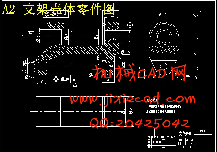
2.1.1 壳体支架的用途 ………………………………………………………… 5
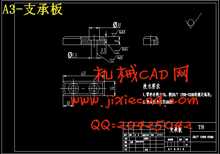
2.1.2 壳体支架的技术要求 ………………………………………………… 6
2.1.3 确定壳体支架的生产类型 …………………………………………… 6
2.2 确定毛坯 ……………………………………………………………………… 6
2.2.1 选择毛坯 ……………………………………………………………… 6
2.2.2 确定毛坯的尺寸公差和机械加工余量 ……………………………… 7
2.3 拟定支架壳体工艺路线 ……………………………………………………… 7
2.3.1 定位基准的选择 ……………………………………………………… 7
2.3.2 各表面加工方案的确定 ……………………………………………… 7
2.3.3 加工阶段的划分 ……………………………………………………… 7
2.3.4 工序的集中与分散 …………………………………………………… 8
2.3.5 工序顺序的安排 ……………………………………………………… 8
2.3.6 机床设备及工艺装备的选用 ………………………………………… 9
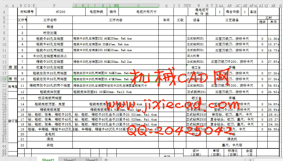
2.3.7 确定工艺路线 ………………………………………………………… 9
2.4 确定加工余量和工序尺寸 ………………………………………………… 10
2.4.1 工序3和工序4——加工Φ20孔两端面至设计尺寸 ………………… 10
2.4.2 工序5和工序7——加工Φ35孔右端面至设计尺寸 ……………… 12
2.4.3 工序9和工序11——加工左侧Φ20孔两端面至设计尺寸 …………… 14
2.4.4 工序10和工序11——加工右侧Φ20孔两端面至设计尺寸 ………… 16
2.4.5 工序12——加工壳体侧面至设计尺寸 ……………………………… 18
2.4.6 工序14和工序15——加工底板两端面至设计尺寸 ……………… 20
2.4.7 工序16——钻、粗铰、精铰Φ20孔 ………………………………… 22
2.4.8 工序17——钻、粗铰、精铰Φ40孔 ………………………………… 23
2.5 确定切削用量及时间定额 ………………………………………………… 24
2.5.1 确定切削用量 ………………………………………………………… 24
2.5.2 时间定额的计算 ……………………………………………………… 26
第三章 专用夹具设计 ……………………………………………………… 30
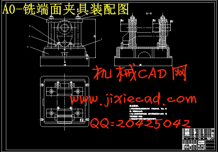
3.1 铣床夹具设计 ………………………………………………………………… 30
3.1.1 铣床夹具的设计要点 ………………………………………………… 30
3.1.2 定位基准的选择和定位误差的分析 ………………………………… 30
3.1.3 铣削力和夹紧力的计算 ………………………………………………31
3.1.4 夹具的结构组成 ………………………………………………………32
3.1.5 夹具的操作方法 …………………………………………………… 33
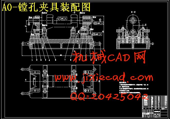
3.2 镗床夹具设计 ……………………………………………………………… 33
3.2.1 镗床夹具的设计要点 ……………………………………………… 33
3.2.2 镗床夹具的结构分析和误差分析 ………………………………… 37
3.2.3 切削力和夹紧力的计算 …………………………………………… 39
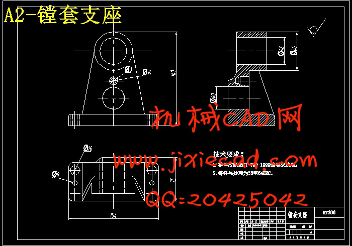
3.2.4 镗床夹具的结构组成 ……………………………………………… 40
第四章 总结 ………………………………………………………………… 41
致谢 ……………………………………………………………………………… 43
参考文献 …………………………………………………………………………44