设计简介
摘 要
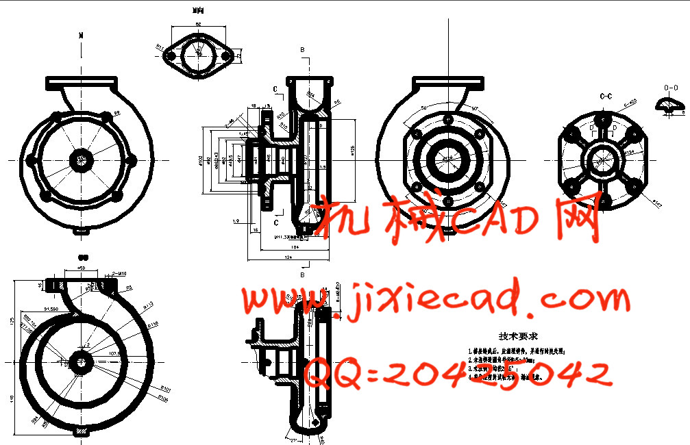
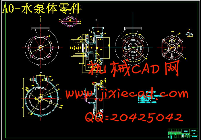
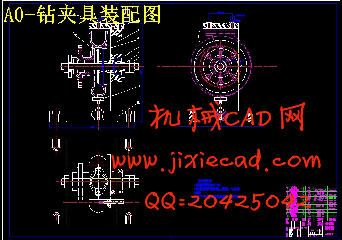
在机床上加工工件时,定位和夹紧的全过程称为“安装”。在机床上用来完成工件安装任务的重要工艺装备,就是各类夹具中应用最为广泛的“机床夹具”。机床夹具的种类很多,其中,使用范围最广的通用夹具,规格尺寸多已标准化,并且有专业的工厂进行生产。而广泛用于批量生产,专为某工件加工工序服务的专用夹具,则需要各制造厂根据工件加工工艺自行设计制造。本设计的主要内容是设计钻床夹具,需要对泵体上表面4xM6的四个螺纹孔进行钻削。
泵体零件上往往都有各种不同用途和不同精度的孔需要加工。在机械加工中,孔的加工量所占比例较大,其中钻头、扩孔钻、铰刀、镗刀等定尺寸刀具加工占相当多数。这时,除了要保证孔的尺寸精度外,还要达到孔的位置精度要求。在单件小批量生产中,用划线后找正孔轴线位置方法加工。在批量生产中一般都采用钻床夹具与镗床夹具,钻床夹具又称钻模,镗床夹具又称镗模,通过钻套、镗套引导刀具进行加工可准确地确定刀具与工件之间的相对位置。
关键词: 通用夹具; 专用夹具; 钻床夹具; 泵体
Abstract
In the machine machining, positioning and clamping process called "installation". The machine used to complete the task of workpiece installation of process equipment, is an important fixture in the most widely used "the machine tool's fixture.There are many kinds of the machine tool's fixture, among them, use the widest range of general fixture, size, and there has been more standardized professional factory production. And widely used in mass production, designed for a workpiece machining processes and special fixture service to the factory according to the workpiece machining process to design and manufacture. The design of the main content is boring and milling machine fixture design jigs, need to pump body surface 4xM6 of the four threaded hole for drilling.
Pump body parts are usually different purposes and accuracy of the hole machining. In machining, the hole of manufactured, among which the proportion of drilling, reaming, reamer, boring tools for size of such a sizable majority. At this time, except to ensure the accuracy of the size of the hole hole, but also achieve the position precision requirements. In single small batch production, use crossed for positive hole axis position after processing methods. In batch production in general by drilling and boring fixture, drilling fixture and diamond fixture, boring fixture and say, boring, boring set by drilling tools for processing guide can accurately determine tool and the relative position between the workpiece.
Key word: General fixture; Special jig ;Drilling fixture; Pump body
目录
摘 要 IIIAbstract IV
目录 V
1 绪论 1
1.1 课题的背景和意义 1
1.2 机床夹具概述 1
1.2.1 机床夹具 1
1.2.2 机床夹具的功能 1
1.2.3 机床夹具在机械加工中的作用 2
1.2.4 机床夹具的发展趋势 2
2 水泵泵体的工艺规程设计 4
2.1 零件的作用 4
2.2 零件图的审核 4
2.2.1 分析零件图 4
2.2.2 零件的结构工艺性分析 5
2.3 生产过程和工艺过程 5
2.3.1 生产过程 5
2.3.2 工艺过程 6
2.4 工艺规程 7
2.5 零件的工艺分析 7
2.6 选择毛坯 8
2.7 坯料尺寸公差与机械加工余量的确定 8
2.8 确定毛坯尺寸 8
2.9 孔和平面加工分析 8
2.9.1 孔和平面的加工顺序 8
2.9.2 钻孔加工方案选择 8
2.9.3 选择定位基准 9
2.10 基面的选择 10
2.11 零件表面加工方法选择 10
2.12 各工序间加工余量 11
2.13 制定工艺路线 12
2.14 切削用量的计算 13
2.14.1 铣上平面工序切削用量的计算 14
2.14.2 铣下平面工序切削用量的计算 14
2.14.3 铣左端面工序切削用量的计算 15
2.14.4 铣右端面工序切削用量的计算 15
2.14.5 钻Ø48孔工步切削用量的计算 16
2.14.6 加工M10螺纹的切削用量 16
2.14.7 加工M8螺纹的切削用量 17
2.14.8 加工M11.3螺纹的切削用量 18
2.14.9 法兰端面凸台切削用量 19
2.14.10 精车轴承内孔切削用量 19
2.14.11 钻Ø10孔的切削用量 20
2.14.12 左端面倒角的切削用量 20
2.15 机械加工时间定额的确定(参考机械加工工艺手册) 20
2.15.1 机械加工时间定额的组成 20
2.15.2 机械加工时间定额的计算 20
2.15.3 上平面时间定额的计算 21
2.15.4 下平面时间定额的计算 22
2.15.5 左端面时间定额的计算 23
2.15.6 右端面时间定额的计算 24
2.15.7 孔Ø48的时间定额 25
2.15.8 上平面螺纹孔的时间定额 26
2.15.9 左端面Ø10通孔的时间定额 27
2.15.10 下平面英制管螺纹的时间定额 28
2.15.11 右端面螺纹孔的时间定额 29
2.15.12 左端凸台铣平面的时间定额 30
2.15.13 精车轴承内孔的时间定额 31
2.15.14 车左端面倒角的时间定额 32
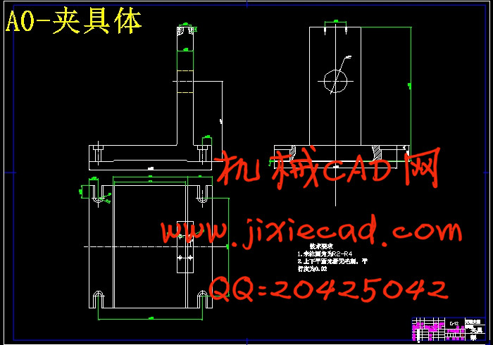
3 夹具设计 33
3.1 对专用夹具的基本要求 33
3.2 专用夹具设计步骤 33
3.3 钻螺纹孔2xM10攻螺纹夹具设计 34
3.3.1 问题的提出 34
3.3.2 夹具设计 34
3.3.3 夹具设计及操作的简要说明 36
4结论与展望 37
4.1 结论 37
4.2 不足之处及未来展望 37
致谢 38
参考文献 39