设计简介
摘 要
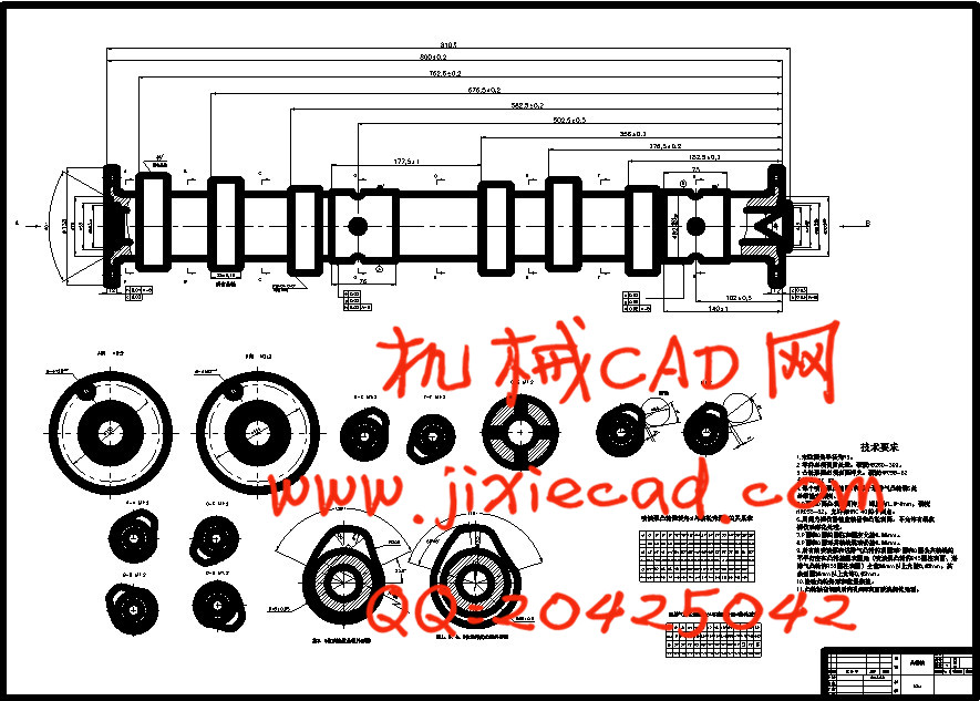
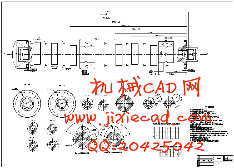
凸轮轴是汽车发动机空气分布机构的关键部件,其性能直接影响整个发动机的性能。凸轮轴的加工工艺有特殊要求,合理处理技术降低处理成本,减少和合理布置凸轮轴生产线具有重要的现实意义。摘要凸轮轴的加工特点,结合工厂的实际情况,从早期的规划、凸轮轴的加工过程进行了深入分析和研究。没有与数控建立建模方法。计算和拆除,凸轮廓形凸轮轮廓处理本文讨论和适用于发动机凸轮轴加工方法被提出。
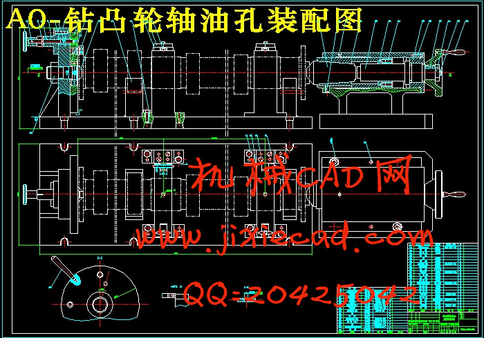
我的 设计主题是凸轮轴过程工具,凸轮轴上的工作要求,部分精度较高,如轴油孔处理,法兰孔加工等等。凸轮轴的过程中,我们试图弄清楚,的基础上保证表达清楚,尽量简洁,在我的设计中,加强了专业机械制造专业知识,学习机械加工过程中,夹具设计、金属切削原理和刀具和金属切削机床。因此,我们设计了两套钻模的设计一些机构,比如划分机制,机构和液压传动机制,等等,并借机器尾座,如大车轮,有利于处理,节省了大量的能量。其中,夹具设计,确保加工表面的位置精度可以减少辅助时间,提高劳动生产率,扩大机床的使用范围,实现工件的夹紧过程和降低劳动强度,改善工作条件,确保安全生产。设计,因为我的水平有限,难免会出现错误,希望读者评论。
关键词:凸轮轴;钻床夹具;分度机构;液压传动机构;发动机;工艺分析
Abstract
凸轮轴是汽车发动机空气分布机构的关键部件,其性能直接影响整个发动机的性能。凸轮轴的加工工艺有特殊要求,合理处理技术降低处理成本,减少和合理布置凸轮轴生产线具有重要的现实意义。摘要凸轮轴的加工特点,结合工厂的实际情况,从早期的规划、凸轮轴的加工过程进行了深入分析和研究。没有与数控建立建模方法。计算和拆除,凸轮廓形凸轮轮廓处理本文讨论和适用于发动机凸轮轴加工方法被提出。
我的 设计主题是凸轮轴过程工具,凸轮轴上的工作要求,部分精度较高,如轴油孔处理,法兰孔加工等等。凸轮轴的过程中,我们试图弄清楚,的基础上保证表达清楚,尽量简洁,在我的设计中,加强了专业机械制造专业知识,学习机械加工过程中,夹具设计、金属切削原理和刀具和金属切削机床。因此,我们设计了两套钻模的设计一些机构,比如划分机制,机构和液压传动机制,等等,并借机器尾座,如大车轮,有利于处理,节省了大量的能量。其中,夹具设计,确保加工表面的位置精度可以减少辅助时间,提高劳动生产率,扩大机床的使用范围,实现工件的夹紧过程和降低劳动强度,改善工作条件,确保安全生产。设计,因为我的水平有限,难免会出现错误,希望读者评论。
关键词:凸轮轴;钻床夹具;分度机构;液压传动机构;发动机;工艺分析
Abstract
The camshaft is the key components of automobile engine air distribution mechanism, its performance directly affects the whole engine performance. The processing technology of the camshaft have special requirements, reasonable processing technology to reduce processing costs, reduce and reasonable decorate the camshaft production line has important practical significance. Processing characteristics of the CAM shaft, combined with the actual situation of the factory, from the early planning, camshaft machining process is carried on the thorough analysis and research. Not a modeling method with numerical control. Calculation and removal, convex contour CAM contour processing in this paper, we discuss and is suitable for the engine camshaft processing method was put forward.
My graduation design theme is the camshaft process tool, the work requirements of camshaft, part of the high precision, such as shaft oil hole processing, the flange hole processing and so on. In the process of the camshaft, we try to find out, on the basis of the guarantee clear, concise, as far as possible in the design of I, to strengthen the professional machinery manufacturing professional knowledge, learning in the process of machining, fixture design, principles of metal cutting and cutting tools and metal cutting machine tool. As a result, we have designed two sets of jig design some institutions, such as division of mechanism, institution and hydraulic transmission mechanism, and so on, and borrow machine tailstock, such as the big wheel, is advantageous to the processing, saves a lot of energy. Among them, the fixture design, ensure the position precision of the machined surface can reduce the auxiliary time, improve labor productivity, expand the use of the machine tool, the implementation of workpiece clamping process and reduce the labor intensity, improve working conditions, to ensure safety in production. Design, because my level is limited, hard to avoid can appear error, hope the reader comments.
Keyword: The camshaft. Drill jig; Dividing mechanism; Hydraulic transmission mechanism; The engine; Technology analysis
目录
引言My graduation design theme is the camshaft process tool, the work requirements of camshaft, part of the high precision, such as shaft oil hole processing, the flange hole processing and so on. In the process of the camshaft, we try to find out, on the basis of the guarantee clear, concise, as far as possible in the design of I, to strengthen the professional machinery manufacturing professional knowledge, learning in the process of machining, fixture design, principles of metal cutting and cutting tools and metal cutting machine tool. As a result, we have designed two sets of jig design some institutions, such as division of mechanism, institution and hydraulic transmission mechanism, and so on, and borrow machine tailstock, such as the big wheel, is advantageous to the processing, saves a lot of energy. Among them, the fixture design, ensure the position precision of the machined surface can reduce the auxiliary time, improve labor productivity, expand the use of the machine tool, the implementation of workpiece clamping process and reduce the labor intensity, improve working conditions, to ensure safety in production. Design, because my level is limited, hard to avoid can appear error, hope the reader comments.
Keyword: The camshaft. Drill jig; Dividing mechanism; Hydraulic transmission mechanism; The engine; Technology analysis
目录
第一章 零件的功用与结构分析 1
1.1 零件的功用 1
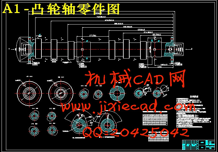
1.2 凸轮轴的结构特点和技术要求 1
1.2.1 各种凸轮轴的技术要求 1
1.2.2 以发动机该凸轮轴为例具体说明 1
第二章 生产类型的确定 2
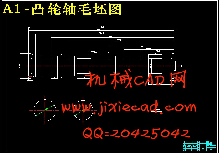
第三章 确定毛坯的种类 4
第四章 机械加工工艺路线的拟定 5
4.1 加工工艺路线的分析 5
4.1.1 凸轮加工工艺分析 6
4.1.2 加工阶段的划分与工序顺序的安排 6
4.1.3 加工工艺路线的拟定 6
4.2 工艺方案比较与分析 8
第五章 确定机械加工余量 工序尺寸及公差 9
第六章 确定切削用量 工件定额切削力及功率 10
6.1 钻孔 10
6.2 扩孔 10
第七章 夹具的设计 12
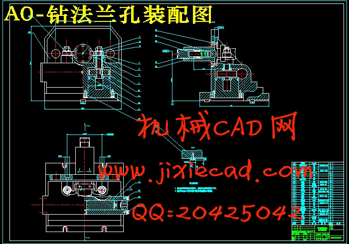
7.1 法兰盘孔的夹具设计 12
7.1.1 工件的加工工艺性分析 12
7.1.1.1、工件属于轴类零件,结构形式简单 12
7.1.1.2、确定定位方案,设计定位元件 13
7.1.1.3、确定设计导向元件 13
7.1.1.4、确定夹紧方式和设计夹紧机构 14
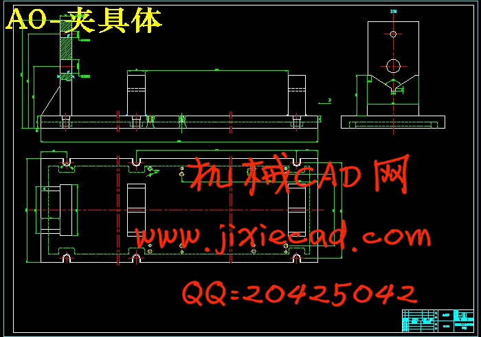
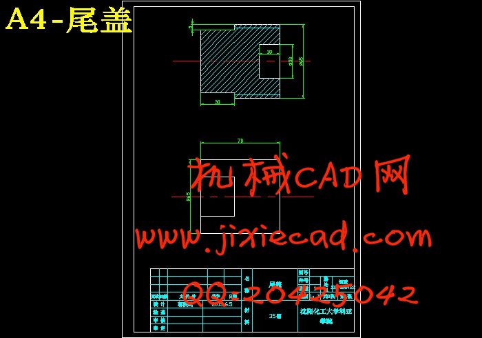
7.1.1.5、确定夹具体 15
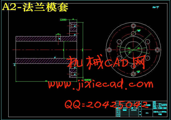
7.1.2 夹具体部件设计分析 15
7.1.2.1、顶尖部分设计 15
7.1.2.2、齿条传动部分设计 15
7.1.2.3、液压缸设计 15
7.2 绘制夹具装配图 16
7.2.1、确定并标注有关尺寸 16
7.2.2、与安装有关的技术要求 16
7.3.3、零件图的技术要求的定制 16
7.3 夹具体的设计步骤 17
7.3.1、研究原始资料,明确设计任务 17
7.3.2、对工件加工工艺的分析 17
7.3.3、夹具设计方案的设计 18
7.7.4、加工精度的分析 18
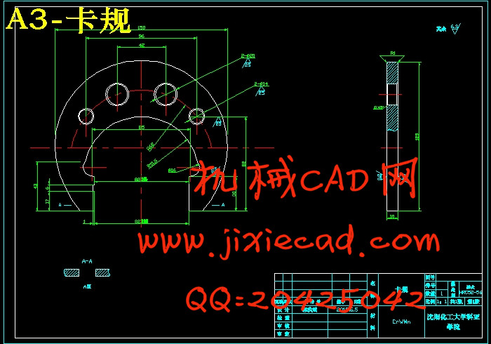
第八章 量规的设计 20
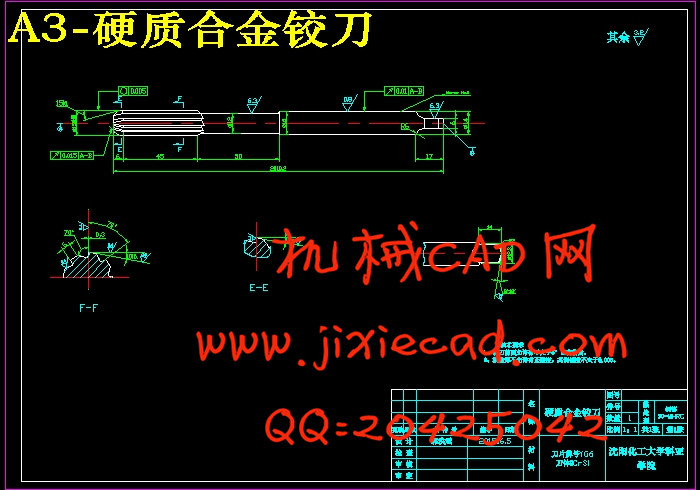
第九章 刀具的设计 21
9.1 铰刀的直径D及直径公差 21
9.2 铰刀的齿数及槽数 21
9.3 铰刀的几何角度 21
9.4 工作部分的尺寸 22
9.5 铰刀非加工部分的结构尺寸 22
第十章 CAD绘图简单说明 23
结论 24
参考文献 25
致谢 26