设计简介
摘要
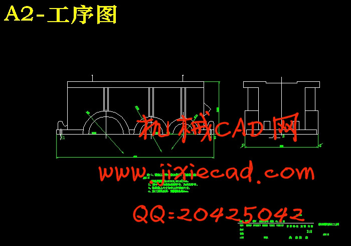
在生产过程中,通过一定的手段使生产对象(原材料,毛坯,零件或总成等)的质和量的状态发生直接变化的过程叫工艺过程。通用减速器机壳体侧面铣削加工工艺装备的设计应该包括确定减速器整体工艺方案的确定,绘制铣削减速器侧面相应的工序图,加工示意图,机床联系尺寸图。被加工零件工序图是根据制定的工艺方案,表示所设计的组合机床上完成的工艺内容,加工部位的尺寸,精度,表面粗糙度及技术要求,加工用的定位基准,夹压部位以及被加工零件的材料,硬度和在本机床加工前加工余量,毛坯的图样,工序图是组合机床设计的具体依据,也是制造,使用,调整和检验机床精度的重要文件。
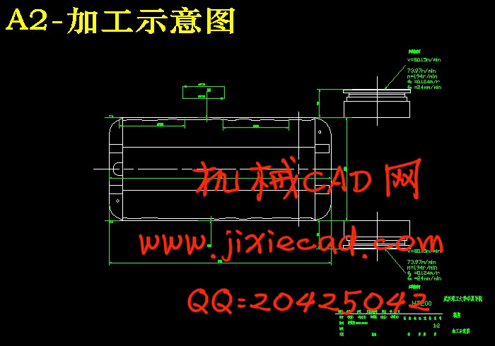
加工示意图是在工艺方案和机床总体方案初步确定的基础上绘制的。是表达工艺方案具有内容的机床工艺方案图。它是设计刀具,辅具,夹具,多轴箱和液压,电器系统以及选择动力部件,绘制机床总联系尺寸图的主要依据;是对机床总体布局和性能的原始要求;也是调整机床和刀具所必须的重要技术文件。
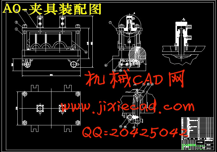
机床联系尺寸图是以被加工零件工序图和加工示意图为依据,并按初步选定的主要通用部件以及确定的专业部件的总体结构而绘制的。是用来表示机床的配置型式,主要构成及各部件安装位置,相互联系,运动关系和操作方位的总体布局图。用来检验各部件相对位置及尺寸联系能否满足加工要求和通用部件选择是否合适;它为多轴箱,夹具等专用部件设计提供重要依据;它可以看成是机床总体外观简图。由轮廓尺寸,占地面积,操作方法等可以检验是否适应用户现场使用环境。夹具图是对组合机床加工布局的完整描述,夹具图反映了工件加工采用定位的方式,夹具方式等一些重要的参数。工艺方案,工序图,加工示意图,机床联系尺寸图,夹具图,工序卡基本构成了完整的加工工艺装备设计。
关键词:工序,工艺分析,定位方案,夹具设计
ABSTRACT
In the production process, through certain means of production object ( raw materials, the blank, part becomealways ) state of quality and quantity directly change process is called process. General reducer casing body side milling technology and equipment design should include identification of reducer overall technology scheme, draw the milling speed reducer side corresponding to the process map, diagram processing, machine tool contact size diagram Is processed the components working procedure chart is formulated according to the process, said the combinatorial machine to complete the process content, processing parts of the size, precision, surface roughness and technical requirements for processing, positioning, clamping part and the part to be machined materials, hardness and in the present before machining allowance, rough pattern, working procedure chart is a combination of machine tool design specific basis, but also manufacturing, use, adjustment and testing accuracy of machine tools and important document. The processing diagram is in process planning and machine overall plan initially identified on the basis of drawing. Is the expression of process scheme with the contents of the machine tool technology scheme. It is a design tool, tool, fixture, spindle and hydraulic, electrical system and the selection of power components, drawing machine total contact size diagram is the main basis of machine; the overall layout and the properties of the original requirements; and adjusting machine tool and cutting tool must have the important technical documents. Machine tool contact size diagram is processed the components working procedure chart and diagram processing as the basis, and according to the preliminary selected major general components and determining the overall structure of the major components and rendering. Is used to indicate the machine configuration type, main components and each component mounting position, mutual connection, movement relation and the operation range of the overall layout. Used to test each component relative position and size of contact can meet the processing requirements and general component selection is appropriate; it is a multiple spindle, fixtures and other special components designed to provide important basis; it can be regarded as the general appearance of machine tool. By the contour size, covers an area of, operation method can test whether adapt to the user application environment on the spot. On the combination of machining fixture graph is a complete description of the layout, fixture graph reflects the workpiece processing using the positioning mode, clamps and some important parameters. Process scheme, process map, diagram processing, machine tool fixture contact size diagram, diagram, working procedure card basic form a complete process equipment design.
Key words: process, process analysis, a positioning scheme, fixture design
目 录
摘要…………………………………………………………………………………………………… 1
abstract …………………………………………………………………………………………… 2
1 绪论 ……………………………………………………………………………………………… 3
2减速器的分析……………………………………………………………………………………… 3
2.1减速器箱座箱盖的分析………………………………………………………………………… 4
2.2箱体零件的加工工艺性………………………………………………………………………… 5
3减速器箱盖,箱座加工工艺方案的确定……………………………………………………………5
3.1加工工艺过程………………………………………………………………………………………5
3.2各表面的加工方案…………………………………………………………………………………6
3.3影响加工方法的因素…………………………………………………………………………… 6
3.4定位基准的确定………………………………………………………………………………… 6
3.4.1粗基准的选择 ……………………………………………………………………………… 6
3.4.2精基准的选择原则…………………………………………………………………………… 7
3.5工艺路线的拟定……………………………………………………………………………………7
4组合机床总体设计-三图一卡……………………………………………………………………… 12
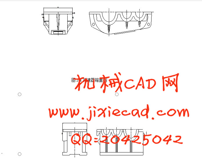
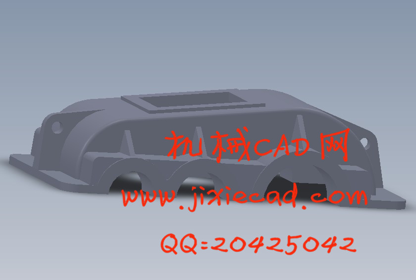
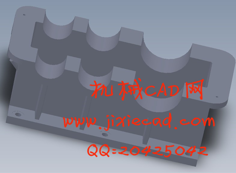
4.1被加工零件工序图……………………………………………………………………………………12
4.2加工示意图……………………………………………………………………………………………14
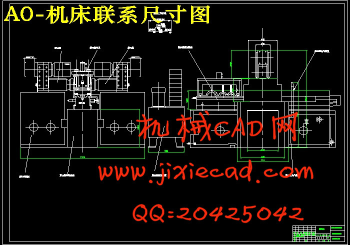
4.3机床联系尺寸图………………………………………………………………………………………18
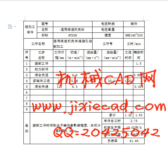
4.4机床生产率计算卡………………………………………………………………………………… 21
5夹具设计………………………………………………………………………………… …………22
6总结………………………………………………………………………………… …………………36
7参考文献………………………………………………………………………………… ……………37
8致谢………………………………………………………………………………… …………………38
在生产过程中,通过一定的手段使生产对象(原材料,毛坯,零件或总成等)的质和量的状态发生直接变化的过程叫工艺过程。通用减速器机壳体侧面铣削加工工艺装备的设计应该包括确定减速器整体工艺方案的确定,绘制铣削减速器侧面相应的工序图,加工示意图,机床联系尺寸图。被加工零件工序图是根据制定的工艺方案,表示所设计的组合机床上完成的工艺内容,加工部位的尺寸,精度,表面粗糙度及技术要求,加工用的定位基准,夹压部位以及被加工零件的材料,硬度和在本机床加工前加工余量,毛坯的图样,工序图是组合机床设计的具体依据,也是制造,使用,调整和检验机床精度的重要文件。
加工示意图是在工艺方案和机床总体方案初步确定的基础上绘制的。是表达工艺方案具有内容的机床工艺方案图。它是设计刀具,辅具,夹具,多轴箱和液压,电器系统以及选择动力部件,绘制机床总联系尺寸图的主要依据;是对机床总体布局和性能的原始要求;也是调整机床和刀具所必须的重要技术文件。
机床联系尺寸图是以被加工零件工序图和加工示意图为依据,并按初步选定的主要通用部件以及确定的专业部件的总体结构而绘制的。是用来表示机床的配置型式,主要构成及各部件安装位置,相互联系,运动关系和操作方位的总体布局图。用来检验各部件相对位置及尺寸联系能否满足加工要求和通用部件选择是否合适;它为多轴箱,夹具等专用部件设计提供重要依据;它可以看成是机床总体外观简图。由轮廓尺寸,占地面积,操作方法等可以检验是否适应用户现场使用环境。夹具图是对组合机床加工布局的完整描述,夹具图反映了工件加工采用定位的方式,夹具方式等一些重要的参数。工艺方案,工序图,加工示意图,机床联系尺寸图,夹具图,工序卡基本构成了完整的加工工艺装备设计。
关键词:工序,工艺分析,定位方案,夹具设计
ABSTRACT
In the production process, through certain means of production object ( raw materials, the blank, part becomealways ) state of quality and quantity directly change process is called process. General reducer casing body side milling technology and equipment design should include identification of reducer overall technology scheme, draw the milling speed reducer side corresponding to the process map, diagram processing, machine tool contact size diagram Is processed the components working procedure chart is formulated according to the process, said the combinatorial machine to complete the process content, processing parts of the size, precision, surface roughness and technical requirements for processing, positioning, clamping part and the part to be machined materials, hardness and in the present before machining allowance, rough pattern, working procedure chart is a combination of machine tool design specific basis, but also manufacturing, use, adjustment and testing accuracy of machine tools and important document. The processing diagram is in process planning and machine overall plan initially identified on the basis of drawing. Is the expression of process scheme with the contents of the machine tool technology scheme. It is a design tool, tool, fixture, spindle and hydraulic, electrical system and the selection of power components, drawing machine total contact size diagram is the main basis of machine; the overall layout and the properties of the original requirements; and adjusting machine tool and cutting tool must have the important technical documents. Machine tool contact size diagram is processed the components working procedure chart and diagram processing as the basis, and according to the preliminary selected major general components and determining the overall structure of the major components and rendering. Is used to indicate the machine configuration type, main components and each component mounting position, mutual connection, movement relation and the operation range of the overall layout. Used to test each component relative position and size of contact can meet the processing requirements and general component selection is appropriate; it is a multiple spindle, fixtures and other special components designed to provide important basis; it can be regarded as the general appearance of machine tool. By the contour size, covers an area of, operation method can test whether adapt to the user application environment on the spot. On the combination of machining fixture graph is a complete description of the layout, fixture graph reflects the workpiece processing using the positioning mode, clamps and some important parameters. Process scheme, process map, diagram processing, machine tool fixture contact size diagram, diagram, working procedure card basic form a complete process equipment design.
Key words: process, process analysis, a positioning scheme, fixture design
目 录
摘要…………………………………………………………………………………………………… 1
abstract …………………………………………………………………………………………… 2
1 绪论 ……………………………………………………………………………………………… 3
2减速器的分析……………………………………………………………………………………… 3
2.1减速器箱座箱盖的分析………………………………………………………………………… 4
2.2箱体零件的加工工艺性………………………………………………………………………… 5
3减速器箱盖,箱座加工工艺方案的确定……………………………………………………………5
3.1加工工艺过程………………………………………………………………………………………5
3.2各表面的加工方案…………………………………………………………………………………6
3.3影响加工方法的因素…………………………………………………………………………… 6
3.4定位基准的确定………………………………………………………………………………… 6
3.4.1粗基准的选择 ……………………………………………………………………………… 6
3.4.2精基准的选择原则…………………………………………………………………………… 7
3.5工艺路线的拟定……………………………………………………………………………………7
4组合机床总体设计-三图一卡……………………………………………………………………… 12
4.1被加工零件工序图……………………………………………………………………………………12
4.2加工示意图……………………………………………………………………………………………14
4.3机床联系尺寸图………………………………………………………………………………………18
4.4机床生产率计算卡………………………………………………………………………………… 21
5夹具设计………………………………………………………………………………… …………22
6总结………………………………………………………………………………… …………………36
7参考文献………………………………………………………………………………… ……………37
8致谢………………………………………………………………………………… …………………38