设计简介
摘 要
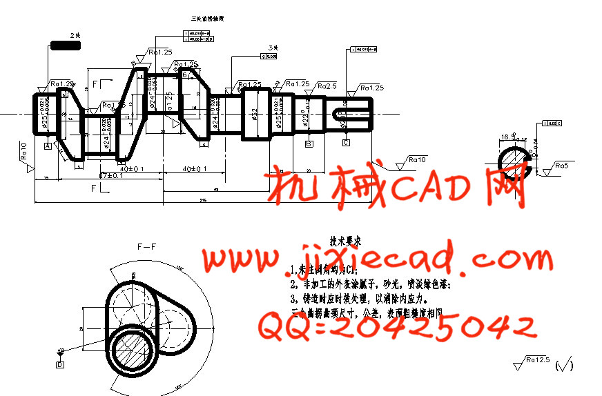
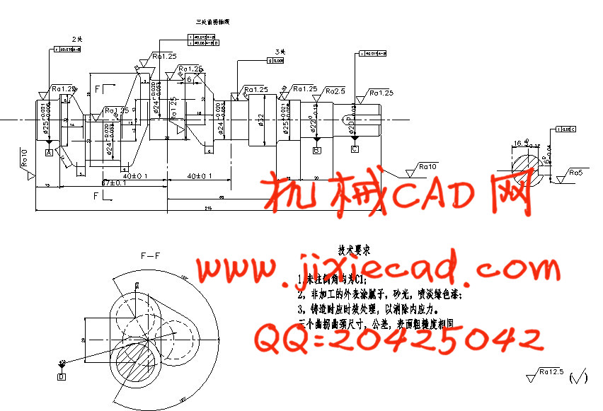
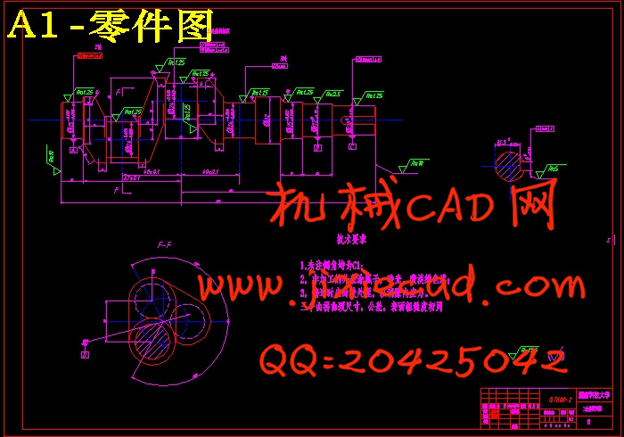
曲轴是发动机的重要零件。它可以是有若干个相互错开一定角度的曲柄(或曲拐)加上功率输出端和自由端构成的。每个曲柄又是由主轴颈、曲柄销及曲柄臂组成。曲轴的作用是把活塞的往复直线运动变成旋转运动,将作用在活塞的气体压力变成扭矩,用来驱动工作机械和发动机各辅助系统进行工作,曲轴在工作时承受着不断变化的力,惯性力和它们的力矩作用,受力情况十分复杂。其精度要求非常高,它的加工质量对内燃机的工作性能,对装配劳动量都有很大影响。因此,各要素的尺寸精度,位置精度和表面质量要求相当高。曲轴中几个主要加工表面,连杆表面,轴承轴颈及锥面键槽的精度要求都较高,连杆轴颈需经过抛光,所以研究曲轴加工工艺及夹具设计对曲轴的生产具有一定的实际意义。
本课题是根据被加工曲轴的技术要求,进行机械加工工艺规程设计,然后运用夹具设计的基本方法,拟定夹具设计方案,完成夹具结构设计。主要工作有:绘制产品零件图,了解零件的结构特点和技术要求,根据生产类型和所在企业的生产条件,对零件进行结构分析和工艺分析,确定毛坯的种类及制造方法;拟定零件的机械加工工艺过程,选择各工序的切削用量和工时定额;填写机械加工工艺过程卡片,机械加工工序卡片等;设计并绘制指定的专用夹具的装配总图和主要零件图。
关键词:曲轴、主轴颈、曲拐
Abstrcat
The crankshaft is one of the important parts of diesel engine. It could be several staggered Angle of crank (or crank) plus the power output end and free end. Each of the cranks is composed of main journal, crank pin and crank arm. Crankshaft is the function of the reciprocating linear motion of the piston into rotary motion, the effect on piston gas pressure become torque, work used to drive machinery and diesel engine work of auxiliary systems, each crankshaft under changing at work force, inertia force and the moment, stress distribution is very complex. Its accuracy is very high, its processing quality of the performance of internal combustion engine, labor has a great influence on assembly. As a result, the size precision of each factor, high position precision and surface quality requirement. Surface of a few main processing surface in the crankshaft, connecting rod, bearing journal and cone keyway accuracy is higher, connecting rod shaft neck should be after polishing, so the processing technology of crankshaft crankshaft production has a certain practical significance.
This topic is according to the requirements of the crankshaft processed technology, carries on the machining process planning design, and then by using the basic method of fixture design, draw up jig design, fixture design. Main work includes: map parts, understand the structure features and technical requirements of the parts, and depending on the type of production in the enterprise production conditions, structural analysis and process analysis of parts, determine the type and manufacturing method of blank; To formulate parts machining process, selection of cutting parameter of each process and task time; Fill in the machining process card, machining process card, etc.; Special fixture design and draw the specified in the general layout and main assembly parts diagram.
Keywords: crankshaft, main journal ,crank
目 录
第一章 绪论 1
1.1本设计的研究内容 1
1.2研究意义 1
第二章 曲轴机械加工工艺规程及工装设计 2
2.1曲轴机械工艺分析及生产类型确定 2
2.1.1曲轴的作用 2
2.1.2曲轴的结构及其特点 2
2.1.3曲轴的主要技术要求分析 2
2.1.4确定离心机主轴的生产类型 3
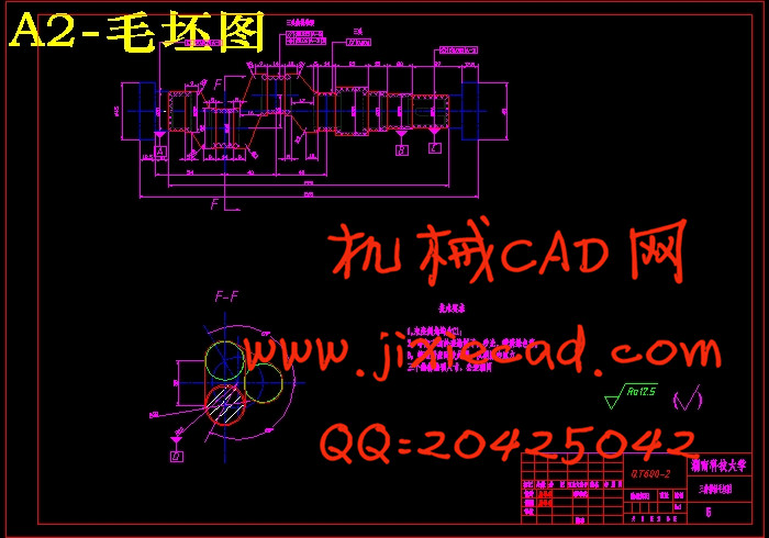
2.2确定毛坯、绘制毛坯简图 4
2.2.1曲轴的材料 4
2.2.2毛坯的确定 4
2.3拟定三拐曲轴的工艺路线 5
2.3.1 三拐曲轴的机械加工工艺特点 5
2.3.2 三拐曲轴的机械加工工艺特点分析 5
2.3.3三拐曲轴的机械加工工艺过程 6
2.3.4三拐曲轴主要加工工序分析 6
2.4确定工序的加工余量,计算工序尺寸及公差 10
2.4.1曲轴主轴颈φ25工序尺寸及公差如表2.3所示 10
2.4.2 曲轴连杆轴颈φ24工序尺寸及公差如表2.4所示 10
2.4.3 曲轴φ220外圆工序尺寸及公差如表2.5所示 11
2.4.4 曲轴φ20外圆工序尺寸及公差如表2.6所示 11
2.5切削用量、时间定额的计算 11
2.5.1 铣工艺搭子左右两端面 11
2.5.2 钻中心孔 13
2.5.3 粗车三个连杆轴颈 13
2.5.4.精车三个连杆轴颈 14
2.5.5 粗车φ25mm轴颈至相应尺寸 15
2.5.6 精车φ25mm轴颈 15
2.5.7 粗车φ22mm轴颈至相应尺寸 16
2.5.8 精车φ22mm轴颈 17
2.5.9 粗车φ20mm轴颈至相应尺寸 17
2.5.10 精车φ20mm轴颈 18
2.5.11 粗车φ32mm轴颈至相应尺寸 19
2.5.12 车掉工艺搭子 19
2.5.13 在主轴颈右端铣键槽 21
2.5.14 磨主轴至要求尺寸 22
2.5.15 磨三个连杆轴颈的切削用量 22
2.5.16 铣左右两端面 23
2.6辅助时间的计算方法 24
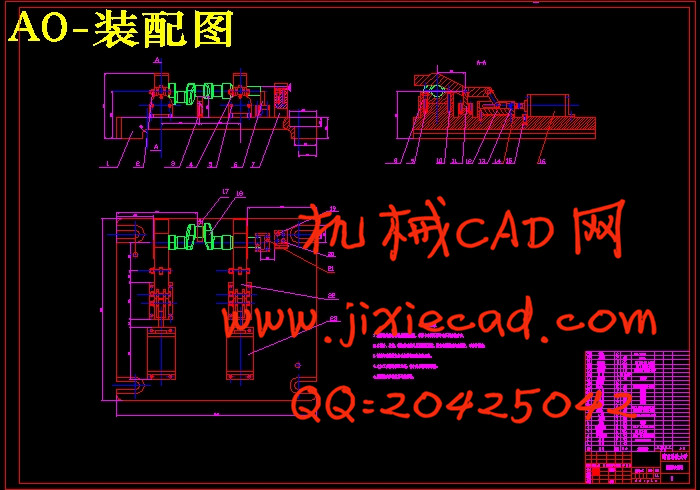
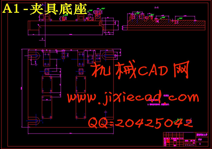
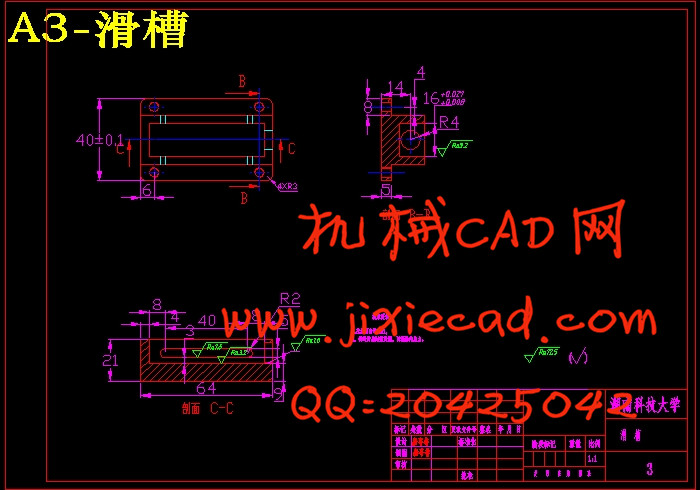
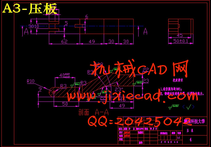
第三章 曲轴铣键槽夹具设计 26
3.1夹具机床的功能 26
3.1.1 保证加工精度 26
3.1.2 提高生产率 26
3.1.3 扩大机床使用的范围 26
3.1.4 减轻工人的劳动强度,保证生产安全 26
3.2夹具机床的类型 26
3.3机床夹具的基本组成 26
3.4工序分析 26
3.5定位方案的确定 27
3.6确定定位元件及夹紧方案 28
3.7夹紧方案的选择 28
3.8夹紧力计算 28
3.8.1铣削力与夹紧力计算 29
3.8.2液压装置的选择与计算 30
3.9定位误差的分析与计算 31
3.9.1定位误差分析 31
3.9.2 产生定位误差的原因 31
3.9.3 与夹具有关的因素产生的定位误差 29
3.10 对刀装置 32
3.11夹具设计设计的简要说明 32
第四章 数控编程 35
4.1数控编程的定义 35
4.2车削数控机床的选择 35
4.3车削数控编程 35
第五章 总结 37
参考文献 38
致 谢 39
曲轴是发动机的重要零件。它可以是有若干个相互错开一定角度的曲柄(或曲拐)加上功率输出端和自由端构成的。每个曲柄又是由主轴颈、曲柄销及曲柄臂组成。曲轴的作用是把活塞的往复直线运动变成旋转运动,将作用在活塞的气体压力变成扭矩,用来驱动工作机械和发动机各辅助系统进行工作,曲轴在工作时承受着不断变化的力,惯性力和它们的力矩作用,受力情况十分复杂。其精度要求非常高,它的加工质量对内燃机的工作性能,对装配劳动量都有很大影响。因此,各要素的尺寸精度,位置精度和表面质量要求相当高。曲轴中几个主要加工表面,连杆表面,轴承轴颈及锥面键槽的精度要求都较高,连杆轴颈需经过抛光,所以研究曲轴加工工艺及夹具设计对曲轴的生产具有一定的实际意义。
本课题是根据被加工曲轴的技术要求,进行机械加工工艺规程设计,然后运用夹具设计的基本方法,拟定夹具设计方案,完成夹具结构设计。主要工作有:绘制产品零件图,了解零件的结构特点和技术要求,根据生产类型和所在企业的生产条件,对零件进行结构分析和工艺分析,确定毛坯的种类及制造方法;拟定零件的机械加工工艺过程,选择各工序的切削用量和工时定额;填写机械加工工艺过程卡片,机械加工工序卡片等;设计并绘制指定的专用夹具的装配总图和主要零件图。
关键词:曲轴、主轴颈、曲拐
Abstrcat
The crankshaft is one of the important parts of diesel engine. It could be several staggered Angle of crank (or crank) plus the power output end and free end. Each of the cranks is composed of main journal, crank pin and crank arm. Crankshaft is the function of the reciprocating linear motion of the piston into rotary motion, the effect on piston gas pressure become torque, work used to drive machinery and diesel engine work of auxiliary systems, each crankshaft under changing at work force, inertia force and the moment, stress distribution is very complex. Its accuracy is very high, its processing quality of the performance of internal combustion engine, labor has a great influence on assembly. As a result, the size precision of each factor, high position precision and surface quality requirement. Surface of a few main processing surface in the crankshaft, connecting rod, bearing journal and cone keyway accuracy is higher, connecting rod shaft neck should be after polishing, so the processing technology of crankshaft crankshaft production has a certain practical significance.
This topic is according to the requirements of the crankshaft processed technology, carries on the machining process planning design, and then by using the basic method of fixture design, draw up jig design, fixture design. Main work includes: map parts, understand the structure features and technical requirements of the parts, and depending on the type of production in the enterprise production conditions, structural analysis and process analysis of parts, determine the type and manufacturing method of blank; To formulate parts machining process, selection of cutting parameter of each process and task time; Fill in the machining process card, machining process card, etc.; Special fixture design and draw the specified in the general layout and main assembly parts diagram.
Keywords: crankshaft, main journal ,crank
目 录
第一章 绪论 1
1.1本设计的研究内容 1
1.2研究意义 1
第二章 曲轴机械加工工艺规程及工装设计 2
2.1曲轴机械工艺分析及生产类型确定 2
2.1.1曲轴的作用 2
2.1.2曲轴的结构及其特点 2
2.1.3曲轴的主要技术要求分析 2
2.1.4确定离心机主轴的生产类型 3
2.2确定毛坯、绘制毛坯简图 4
2.2.1曲轴的材料 4
2.2.2毛坯的确定 4
2.3拟定三拐曲轴的工艺路线 5
2.3.1 三拐曲轴的机械加工工艺特点 5
2.3.2 三拐曲轴的机械加工工艺特点分析 5
2.3.3三拐曲轴的机械加工工艺过程 6
2.3.4三拐曲轴主要加工工序分析 6
2.4确定工序的加工余量,计算工序尺寸及公差 10
2.4.1曲轴主轴颈φ25工序尺寸及公差如表2.3所示 10
2.4.2 曲轴连杆轴颈φ24工序尺寸及公差如表2.4所示 10
2.4.3 曲轴φ220外圆工序尺寸及公差如表2.5所示 11
2.4.4 曲轴φ20外圆工序尺寸及公差如表2.6所示 11
2.5切削用量、时间定额的计算 11
2.5.1 铣工艺搭子左右两端面 11
2.5.2 钻中心孔 13
2.5.3 粗车三个连杆轴颈 13
2.5.4.精车三个连杆轴颈 14
2.5.5 粗车φ25mm轴颈至相应尺寸 15
2.5.6 精车φ25mm轴颈 15
2.5.7 粗车φ22mm轴颈至相应尺寸 16
2.5.8 精车φ22mm轴颈 17
2.5.9 粗车φ20mm轴颈至相应尺寸 17
2.5.10 精车φ20mm轴颈 18
2.5.11 粗车φ32mm轴颈至相应尺寸 19
2.5.12 车掉工艺搭子 19
2.5.13 在主轴颈右端铣键槽 21
2.5.14 磨主轴至要求尺寸 22
2.5.15 磨三个连杆轴颈的切削用量 22
2.5.16 铣左右两端面 23
2.6辅助时间的计算方法 24
第三章 曲轴铣键槽夹具设计 26
3.1夹具机床的功能 26
3.1.1 保证加工精度 26
3.1.2 提高生产率 26
3.1.3 扩大机床使用的范围 26
3.1.4 减轻工人的劳动强度,保证生产安全 26
3.2夹具机床的类型 26
3.3机床夹具的基本组成 26
3.4工序分析 26
3.5定位方案的确定 27
3.6确定定位元件及夹紧方案 28
3.7夹紧方案的选择 28
3.8夹紧力计算 28
3.8.1铣削力与夹紧力计算 29
3.8.2液压装置的选择与计算 30
3.9定位误差的分析与计算 31
3.9.1定位误差分析 31
3.9.2 产生定位误差的原因 31
3.9.3 与夹具有关的因素产生的定位误差 29
3.10 对刀装置 32
3.11夹具设计设计的简要说明 32
第四章 数控编程 35
4.1数控编程的定义 35
4.2车削数控机床的选择 35
4.3车削数控编程 35
第五章 总结 37
参考文献 38
致 谢 39