设计简介
随着机械制造业的不断发展,社会对生产率的要求也越来越高。因此,大批量生产成为时代的需求,而组合机床就可以满足这一需求,我们有必要来研究它。
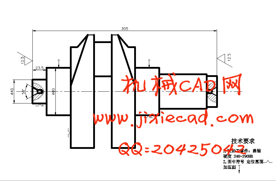
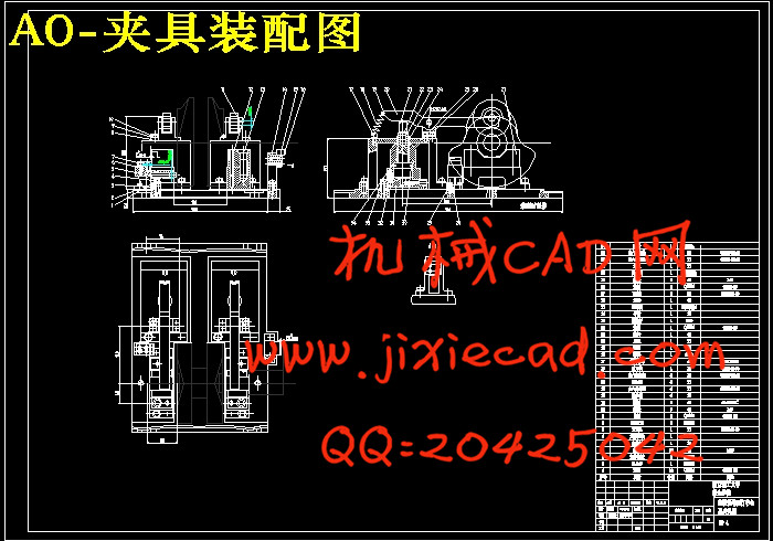
本文中利用组合机床将铣端面和打中心孔在同一道工序中完成,这样可以避免工件在加工不同工序时由于夹紧定位而产生的定位误差。根据所拟定的组合机床的工艺和结构方案,可以定下夹具的结构形式和主要性能。夹具设计的要点是:确保夹具有足够的刚度和强度,降低夹具的重心来提高夹具的稳定性;避免加工时发生振动;夹紧装置有足够的夹紧力和良好的自锁性能;注意采用快速夹紧、联动夹紧、气动液压夹紧装置和机械化传动装置等。
 关键词 曲轴 铣端面 打中心孔 组合机床 专用夹具
Abstract
With the continuous development of the machine manufacturing industry, the productivity of the community's increasing demands.Therefore, high volume production needs of the times, and the combination is enough to meet the needs of machine tool. We need to study it. In this paper,the use of combined machine tool can complete milling the end suferface and punching the central hole at the same procedure. This will avoid the workpiece in different processes arising positioning error as a result of clamping the positioning. According to the combined machined tool technology and the structure that have been studied out, and then the structure and the main properties can be set. The dist of fixture design: Ensure the fixture have sufficient stiffness and strength;Reduce the fixture's center of gravity to improve the stability of fixture. To avoid vibration when machining. Clamping device has sufficient clamping force and a good performance of the self-locking. Attention to the use of rapid clamping, clamping linkage,Hydraulic clamping devices and mechanical transmission devices etc.
Keywords Crankshaft End Suferface Milling Central Hole Punching Combined Machined Tool Special Fixture
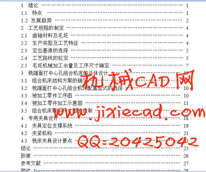
目 次
1 绪论 ………………………………………………………………………… 1
1.1 特点 ……………………………………………………………………… 1
1.2 发展趋势 ……………………………………………………………… 2
2 工艺规程的制定 …………………………………………………………… 4
2.1 曲轴材料及毛坯 ………………………………………………………… 4
2.2 生产类型及工艺特征 …………………………………………………… 4
2.3 定位基准的选择 ………………………………………………………… 5
2.4 工艺路线的拟定 ………………………………………………………… 5
2.5 毛坯机械加工余量及工序尺寸确定 …………………………………… 7
3 铣端面打中心孔组合机床的总体设计 …………………………………… 10
3.1 组合机床结构方案的确定 ……………………………………………… 10
3.2 铣端面打中心孔组合机床配置型式的选择 …………………………… 10
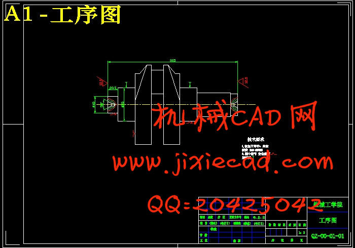
3.3 被加工零件工序图 ……………………………………………………… 10
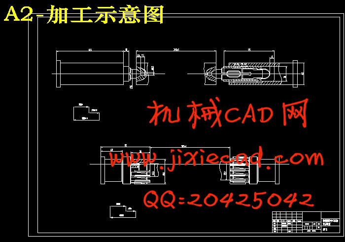
3.4 被加工零件加工示意图 ………………………………………………… 11
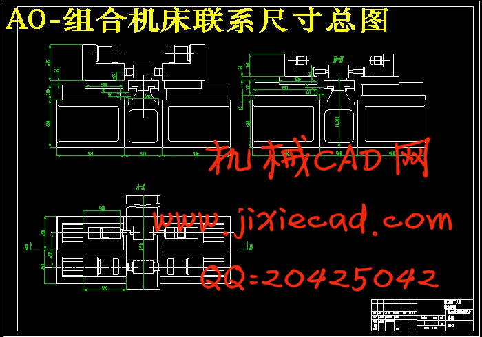
3.5 组合机床联系尺寸图的绘制 …………………………………………… 13
4 专用夹具设计 ……………………………………………………………… 18
4.1 夹具定位支撑系统 ……………………………………………………… 18
4.2 夹紧机构 ………………………………………………………………… 21
4.3 铣床夹具设计要点 ……………………………………………………… 23
结论 …………………………………………………………………………… 25
致谢 …………………………………………………………………………… 26
参考文献 ……………………………………………………………………… 27
本文中利用组合机床将铣端面和打中心孔在同一道工序中完成,这样可以避免工件在加工不同工序时由于夹紧定位而产生的定位误差。根据所拟定的组合机床的工艺和结构方案,可以定下夹具的结构形式和主要性能。夹具设计的要点是:确保夹具有足够的刚度和强度,降低夹具的重心来提高夹具的稳定性;避免加工时发生振动;夹紧装置有足够的夹紧力和良好的自锁性能;注意采用快速夹紧、联动夹紧、气动液压夹紧装置和机械化传动装置等。
Abstract
With the continuous development of the machine manufacturing industry, the productivity of the community's increasing demands.Therefore, high volume production needs of the times, and the combination is enough to meet the needs of machine tool. We need to study it. In this paper,the use of combined machine tool can complete milling the end suferface and punching the central hole at the same procedure. This will avoid the workpiece in different processes arising positioning error as a result of clamping the positioning. According to the combined machined tool technology and the structure that have been studied out, and then the structure and the main properties can be set. The dist of fixture design: Ensure the fixture have sufficient stiffness and strength;Reduce the fixture's center of gravity to improve the stability of fixture. To avoid vibration when machining. Clamping device has sufficient clamping force and a good performance of the self-locking. Attention to the use of rapid clamping, clamping linkage,Hydraulic clamping devices and mechanical transmission devices etc.
Keywords
目 次
1 绪论 ………………………………………………………………………… 1
1.1 特点 ……………………………………………………………………… 1
1.2 发展趋势 ……………………………………………………………… 2
2 工艺规程的制定 …………………………………………………………… 4
2.1 曲轴材料及毛坯 ………………………………………………………… 4
2.2 生产类型及工艺特征 …………………………………………………… 4
2.3 定位基准的选择 ………………………………………………………… 5
2.4 工艺路线的拟定 ………………………………………………………… 5
2.5 毛坯机械加工余量及工序尺寸确定 …………………………………… 7
3 铣端面打中心孔组合机床的总体设计 …………………………………… 10
3.1 组合机床结构方案的确定 ……………………………………………… 10
3.2 铣端面打中心孔组合机床配置型式的选择 …………………………… 10
3.3 被加工零件工序图 ……………………………………………………… 10
3.4 被加工零件加工示意图 ………………………………………………… 11
3.5 组合机床联系尺寸图的绘制 …………………………………………… 13
4 专用夹具设计 ……………………………………………………………… 18
4.1 夹具定位支撑系统 ……………………………………………………… 18
4.2 夹紧机构 ………………………………………………………………… 21
4.3 铣床夹具设计要点 ……………………………………………………… 23
结论 …………………………………………………………………………… 25
致谢 …………………………………………………………………………… 26
参考文献 ……………………………………………………………………… 27