设计简介
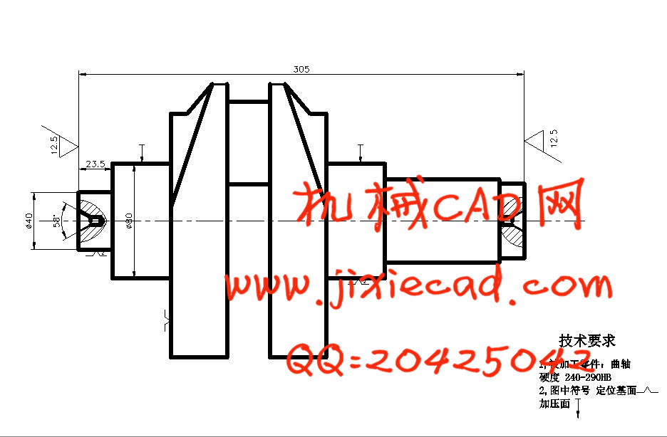
曲轴铣端面打中心孔机床总体设计及夹具设计
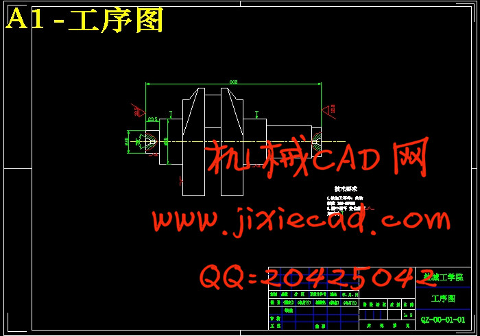
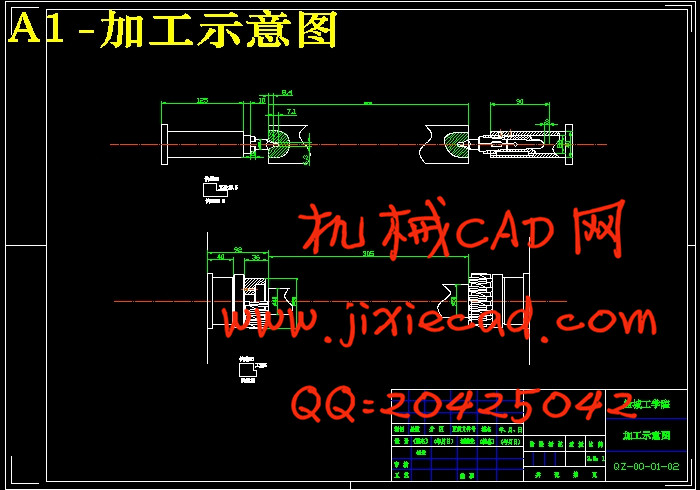
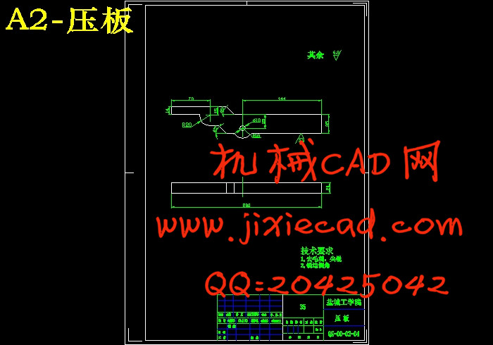
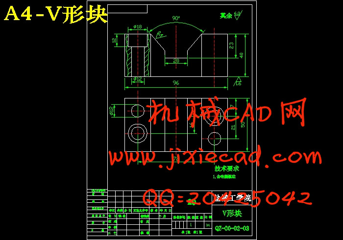
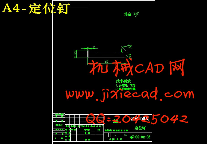
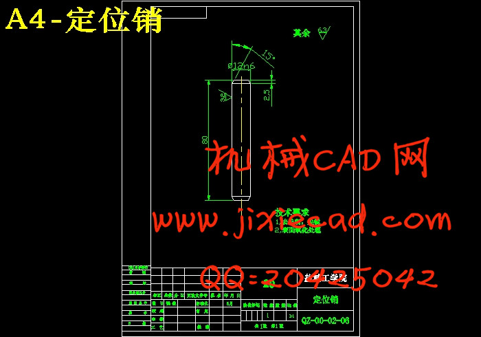
摘 要:应用组合机床大批大量生产零件,快捷高效,生产效率是机械加工的发展方向。为了提高加工精度,需要设计一台组合机床来改善曲轴的加工情况。本课题是曲轴铣端面打中心孔组合机床的总体设计及夹具设计。主要完成对曲轴左右两个端面的铣削及中心孔的钻削,还要完成其专用夹具的设计。本设计的组合机床为卧式双面铣削和钻削组合机床,先对被加工零件特点进行分析,选择采用刀具和工件分别安装在各自滑台上的方法,先铣后钻。在确定了机床配置型式的基础上,根据本道工序需要加工的内容,完成三图一卡的设计。夹具部分的设计主要是定位和夹紧方式的选择,以零件加工工序图为基础,该零件由两V形块在两主轴颈处定位,限制四个自由度,为防止工件的轴向移动,用一个定位钉在扇形板左端面处定位。夹紧方式采用液压夹紧,力源装置为液压缸,中间递力机构为推杆,夹紧元件为压板。操作简单,易于集中控制,夹紧可靠。
关键词:组合机床;总体设计;三图一卡;定位夹紧
The overall design of the face milling and drill center hole
machine toll and fixture design
Abstract: Application of mass production of large machine tool parts, fast and efficient, production efficiency is the development direction of machining.To improve the precision needed to design a machine tool to improve the situation of the crankshaft machining.The issue is the crankshaft end play center hole milling machine tool's overall design.Completion of the crankshaft main left and right end of the milling and drilling the center hole, but also to complete the design of the special fixture.The design of the combination machine is a horizontal double-sided milling and drilling machine tool, the first part of the analysis of the characteristics to be processed, choose the tool and workpiece were installed in each stage of the method of sliding, after the first milling drill.In determining the types of machine configurations based on the needs of the procedure for processing the contents of one card to complete the design of the three plans.Clamping hydraulic clamping, power source device for hydraulic cylinders, force agencies to putting the middle of delivery, the clamping device for the clips. Simple, easy centralized control, reliable clamping.
Key word: Machine Tool; Overall design; Three diagram and a card; Locating and clamping
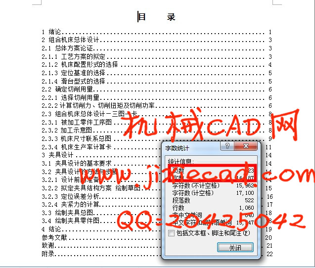
目 录
1 绪论 1
2 组合机床总体设计 3
2.1 总体方案论证 3
2.1.1 工艺方案的拟定 3
2.1.2 机床配置形式的选择 4
2.1.3 定位基准的选择 5
2.1.4 滑台型式的选择 5
2.2 确定切削用量 6
2.2.1 选择切削用量 6
2.2.2计算切削力、切削扭矩及切削功率 6
2.3 组合机床总体设计—三图一卡 8
2.3.1 被加工零件工序图 8
2.3.2 加工示意图 8
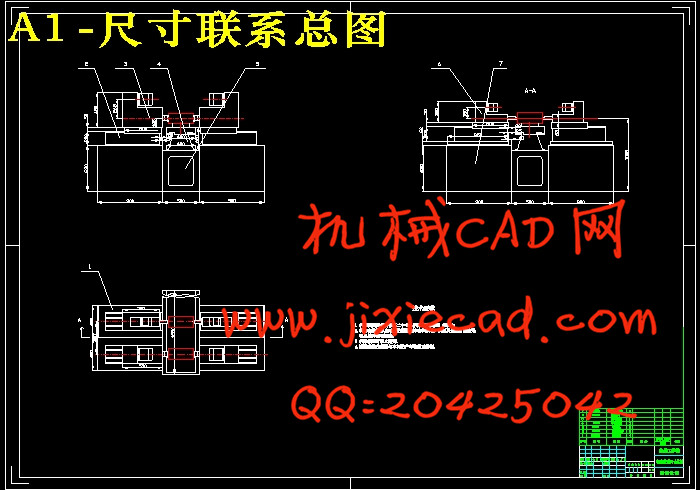
2.3.3 机床尺寸联系总图 9
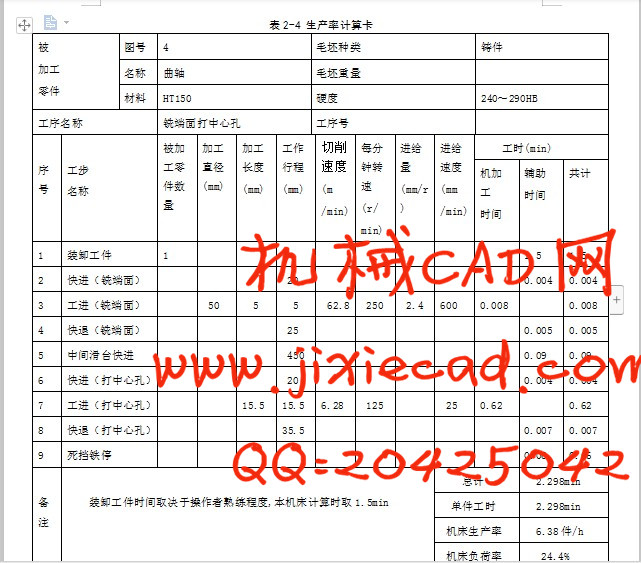
2.3.4 机床生产率计算卡 11
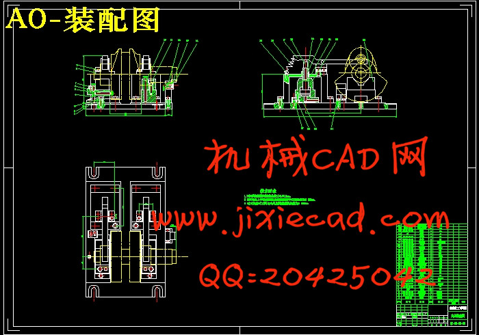
3 夹具设计 14
3.1 夹具设计的基本要求 14
3.2 夹具设计的方法与步骤 14
3.2.1 设计前的准备 14
3.2.2 拟定夹具结构方案 绘制草图 15
3.2.3 定位误差分析.................................................... 16
3.2.4 夹紧力的计算.................................................... 17
3.3 绘制夹具总图 18
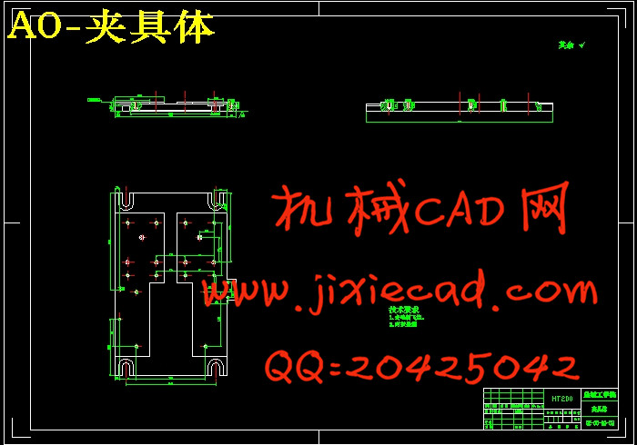
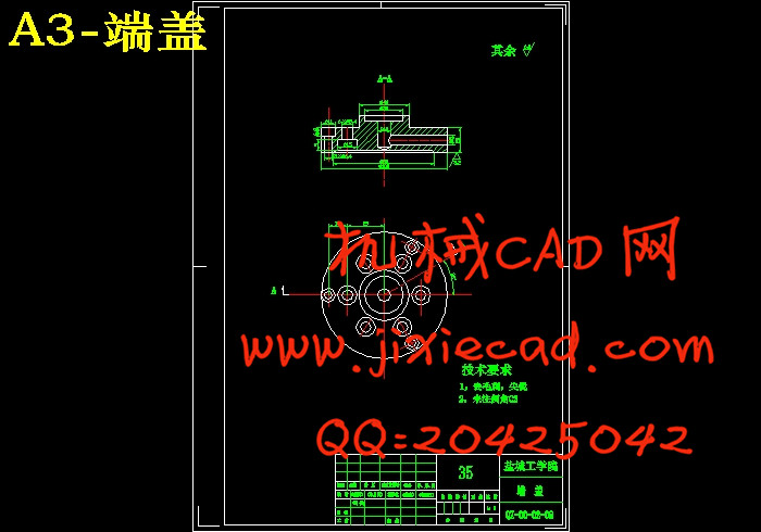
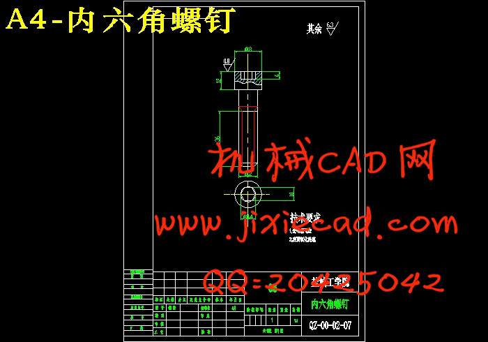
3.4 绘制夹具零件图 18
4 结论 19
参考文献 20
致谢.................................................................. 21
附录.................................................................. 22
摘 要:应用组合机床大批大量生产零件,快捷高效,生产效率是机械加工的发展方向。为了提高加工精度,需要设计一台组合机床来改善曲轴的加工情况。本课题是曲轴铣端面打中心孔组合机床的总体设计及夹具设计。主要完成对曲轴左右两个端面的铣削及中心孔的钻削,还要完成其专用夹具的设计。本设计的组合机床为卧式双面铣削和钻削组合机床,先对被加工零件特点进行分析,选择采用刀具和工件分别安装在各自滑台上的方法,先铣后钻。在确定了机床配置型式的基础上,根据本道工序需要加工的内容,完成三图一卡的设计。夹具部分的设计主要是定位和夹紧方式的选择,以零件加工工序图为基础,该零件由两V形块在两主轴颈处定位,限制四个自由度,为防止工件的轴向移动,用一个定位钉在扇形板左端面处定位。夹紧方式采用液压夹紧,力源装置为液压缸,中间递力机构为推杆,夹紧元件为压板。操作简单,易于集中控制,夹紧可靠。
关键词:组合机床;总体设计;三图一卡;定位夹紧
The overall design of the face milling and drill center hole
machine toll and fixture design
Abstract: Application of mass production of large machine tool parts, fast and efficient, production efficiency is the development direction of machining.To improve the precision needed to design a machine tool to improve the situation of the crankshaft machining.The issue is the crankshaft end play center hole milling machine tool's overall design.Completion of the crankshaft main left and right end of the milling and drilling the center hole, but also to complete the design of the special fixture.The design of the combination machine is a horizontal double-sided milling and drilling machine tool, the first part of the analysis of the characteristics to be processed, choose the tool and workpiece were installed in each stage of the method of sliding, after the first milling drill.In determining the types of machine configurations based on the needs of the procedure for processing the contents of one card to complete the design of the three plans.Clamping hydraulic clamping, power source device for hydraulic cylinders, force agencies to putting the middle of delivery, the clamping device for the clips. Simple, easy centralized control, reliable clamping.
Key word: Machine Tool; Overall design; Three diagram and a card; Locating and clamping
目 录
1 绪论 1
2 组合机床总体设计 3
2.1 总体方案论证 3
2.1.1 工艺方案的拟定 3
2.1.2 机床配置形式的选择 4
2.1.3 定位基准的选择 5
2.1.4 滑台型式的选择 5
2.2 确定切削用量 6
2.2.1 选择切削用量 6
2.2.2计算切削力、切削扭矩及切削功率 6
2.3 组合机床总体设计—三图一卡 8
2.3.1 被加工零件工序图 8
2.3.2 加工示意图 8
2.3.3 机床尺寸联系总图 9
2.3.4 机床生产率计算卡 11
3 夹具设计 14
3.1 夹具设计的基本要求 14
3.2 夹具设计的方法与步骤 14
3.2.1 设计前的准备 14
3.2.2 拟定夹具结构方案 绘制草图 15
3.2.3 定位误差分析.................................................... 16
3.2.4 夹紧力的计算.................................................... 17
3.3 绘制夹具总图 18
3.4 绘制夹具零件图 18
4 结论 19
参考文献 20
致谢.................................................................. 21
附录.................................................................. 22