设计简介
毕 业 设 计论 文 任 务 书
一、题目及专题:
1、题目 内燃机连杆加工工艺及夹具设计
2、专题
二、课题来源及选题依据
课题来源于生产实际。
内燃机行业是我国机械工业中跨行业、跨部门最多的一个行业,内燃机是汽车、工程机械、农业机械、船舶、内燃机车、内燃发电设备、地质石油钻机、军用、各种通用机械等产品的配套动力,是各种配套产品的“心脏”。因此,内燃机行业的发展,对我国工业、交通运输、农业、国防建设,以及人民生活都有十分重大的影响。
工艺是机械产品设计、制造过程中的重要组成部分。工艺设计的好坏直接影响产品的最终制造质量和整个生产系统的优化状况。
三、本设计(论文或其他)应达到的要求:
1.通过该设计使学生熟悉零件加工工艺设计和夹具设计的一般思路。
2.使学生掌握一般零件加工工艺设计和夹具设计的方法和技巧。
3.通过设计巩固机械制图、金属材料、机械设计基础、机械制造工艺等课程的知识。
4.完成连杆零件工艺设计、主要部件的参数计算及标准件的选用。
5.机械加工工艺过程卡片及工序卡1套
6.完成夹具零、部件图8张以上。
7.完成夹具总装图1张。
8.撰写毕业说明书一份。
①计算正确完整,文字简洁通顺,书写整齐清晰。
②论文中所引用的公式和数据应注明出处。
③论文字数不少于1.5万字。
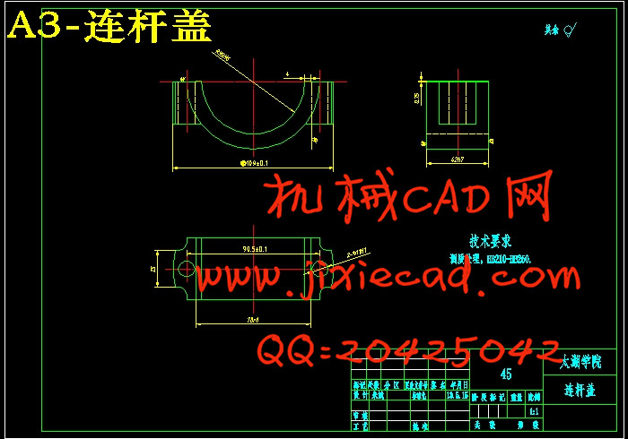
9. 内燃机连杆毛坯图、零件图及技术要求见图纸。
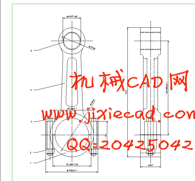
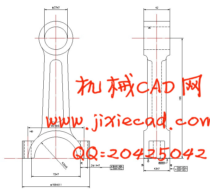
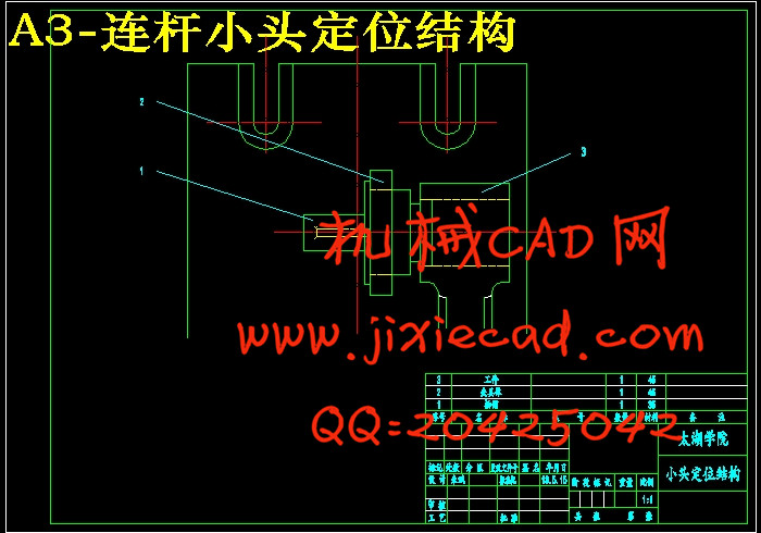
连杆是内燃机的主要传动件之一,正文主要论述了连杆的加工工艺及夹具设计。连杆的尺寸精度、形状精度以及位置精度的要求都很高,而连杆的刚性比较差,容易产生变形,因此在安排工艺过程时需要把各主要表面的粗精加工工序分开。逐步减少连杆加工余量、切削力及内应力的作用,以及修正加工后的变形,最后就能达到连杆的技术要求。连杆的主要加工表面为大、小头孔和两端面,较重要的加工表面为连杆体和盖的结合面及连杆螺栓孔定位面,次要加工表面为大头两侧面及螺栓座面等。
在连杆加工中有两个主要因素影响加工精度:
(1)连杆本身的刚度比较低,在外力(夹紧力、切削力)的作用下容易变形。
(2)连杆是模锻件,孔的加工余量较大,切削时将产生较大的残余内应力,并引起内应力重新分布。
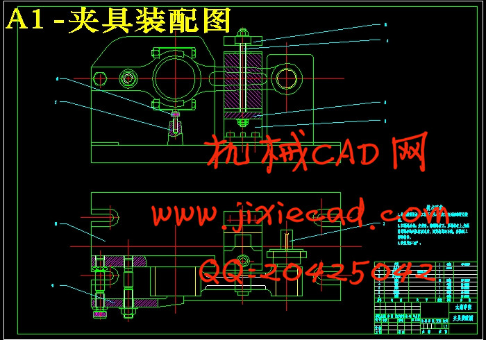
通过对内燃机连杆的机械加工工艺及对粗加工大头孔夹具和铣结合面夹具的设计,主要归纳为以下两个方面:
第一方面:连杆件外形较复杂,而刚性较差。其技术要求很高,所以适当的选择机械加工中的定位基准,是能否保证连杆技术要求的重要问题之一。在连杆的实际加工过程中,选用连杆的大小头端面及小头孔作为主要定位基面,同时选用大头孔两侧面作为一般定位基准。为保证小头孔尺寸精度和形状精度,可采用自为基准的加工原则;保证大小头孔的中心距精度要求,可采用互为基准原则加工。
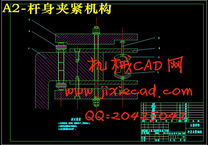
第二方面:关于夹具的设计方法及其步骤。
关键词:连杆;变形;加工工艺;夹具设计
The connecting rod is one of the main driving medium of diesel engine, this text expounds mainly the machining technology and the design of clamping device of the connecting rod. The precision of size, the precision of profile and the precision of position , of the connecting rod is demanded highly , and the rigidity of the connecting rod is not enough, easy to deform, so arranging the craft course, need to separate the each main and superficial thick finish machining process. Reduce the margin of processing, cutting force and internal stress progressively, revise the deformation after processing, can reach the specification requirement for the part finally .
In the Connecting rod is one of the main processing surface is large, the small head hole and both ends of the machined surface, is important for the connecting rod body and cover joint surface and the connecting rod bolt hole locating surface, secondary processing surface for bearing locking grooves, oil hole, head and body and a cover on the two sides of the bolt seat surface.
Machine of connecting rod are two major factors that affect the machining precision:
(1) Connecting rod itself stiffness is relatively low, in the external forces (cutting force, clamping force ) under the action of easy deformation.
(2) Connecting rod is die forgings, hole machining allowance, cutting will produce bigger residual stress, and stress redistribution caused by.
The automobile connecting rod machining process and the rough machining and milling combined with big hole clamp surface fixture design, mainly divided into the following two aspects:
The first aspect: connecting rod parts with complicated shape, while the poor rigidity. And the very high technical requirements, so the appropriate selection of mechanical processing in the locating datum, can ensure the connecting rod is one of the important problems of technical requirements. The connecting rod in the practical production process, selection of connecting rod to the size of the head end and the small head hole as the main positioning datum, and choice of big hole two side as a general locating datum. In order to ensure the size precision and shape precision of the small head hole, can be used for reference from the processing principle; ensure that the size of the first hole center distance accuracy requirements, can be used for reference each other the principle of processing.
Second: mainly on the fixture design method and steps.
Key words: Connecting rod;Deformation;Process;Fixture design
3.5.13 精磨两端平面 21
3.5.14 精镗小头孔 21
3.5.15 粗镗大头孔 22
3.5.16 精镗大头孔 22
3.5.17 精镗小头孔 22
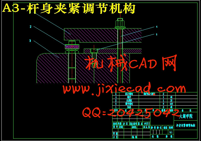
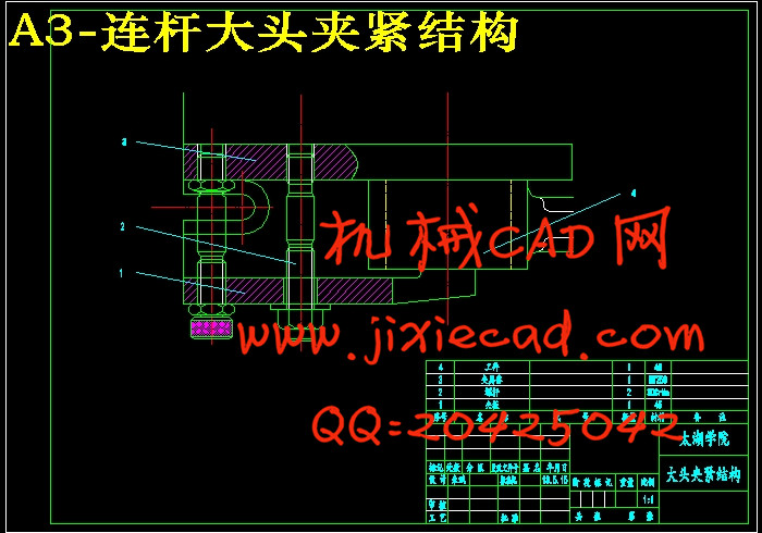
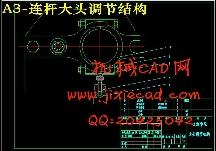
4 夹具设计 23
4.1 机床夹具的分类 22
4.2 工件的加工工艺分析 23
4.3 确定定位方案 23
4.4 夹具的机构设计 24
4.5 夹具的使用 26
5 结论与展望 28
6 致谢 29
7.参考文献 30
一、题目及专题:
1、题目 内燃机连杆加工工艺及夹具设计
2、专题
二、课题来源及选题依据
课题来源于生产实际。
内燃机行业是我国机械工业中跨行业、跨部门最多的一个行业,内燃机是汽车、工程机械、农业机械、船舶、内燃机车、内燃发电设备、地质石油钻机、军用、各种通用机械等产品的配套动力,是各种配套产品的“心脏”。因此,内燃机行业的发展,对我国工业、交通运输、农业、国防建设,以及人民生活都有十分重大的影响。
工艺是机械产品设计、制造过程中的重要组成部分。工艺设计的好坏直接影响产品的最终制造质量和整个生产系统的优化状况。
三、本设计(论文或其他)应达到的要求:
1.通过该设计使学生熟悉零件加工工艺设计和夹具设计的一般思路。
2.使学生掌握一般零件加工工艺设计和夹具设计的方法和技巧。
3.通过设计巩固机械制图、金属材料、机械设计基础、机械制造工艺等课程的知识。
4.完成连杆零件工艺设计、主要部件的参数计算及标准件的选用。
5.机械加工工艺过程卡片及工序卡1套
6.完成夹具零、部件图8张以上。
7.完成夹具总装图1张。
8.撰写毕业说明书一份。
①计算正确完整,文字简洁通顺,书写整齐清晰。
②论文中所引用的公式和数据应注明出处。
③论文字数不少于1.5万字。
9. 内燃机连杆毛坯图、零件图及技术要求见图纸。
摘 要
连杆是内燃机的主要传动件之一,正文主要论述了连杆的加工工艺及夹具设计。连杆的尺寸精度、形状精度以及位置精度的要求都很高,而连杆的刚性比较差,容易产生变形,因此在安排工艺过程时需要把各主要表面的粗精加工工序分开。逐步减少连杆加工余量、切削力及内应力的作用,以及修正加工后的变形,最后就能达到连杆的技术要求。连杆的主要加工表面为大、小头孔和两端面,较重要的加工表面为连杆体和盖的结合面及连杆螺栓孔定位面,次要加工表面为大头两侧面及螺栓座面等。
在连杆加工中有两个主要因素影响加工精度:
(1)连杆本身的刚度比较低,在外力(夹紧力、切削力)的作用下容易变形。
(2)连杆是模锻件,孔的加工余量较大,切削时将产生较大的残余内应力,并引起内应力重新分布。
通过对内燃机连杆的机械加工工艺及对粗加工大头孔夹具和铣结合面夹具的设计,主要归纳为以下两个方面:
第一方面:连杆件外形较复杂,而刚性较差。其技术要求很高,所以适当的选择机械加工中的定位基准,是能否保证连杆技术要求的重要问题之一。在连杆的实际加工过程中,选用连杆的大小头端面及小头孔作为主要定位基面,同时选用大头孔两侧面作为一般定位基准。为保证小头孔尺寸精度和形状精度,可采用自为基准的加工原则;保证大小头孔的中心距精度要求,可采用互为基准原则加工。
第二方面:关于夹具的设计方法及其步骤。
关键词:连杆;变形;加工工艺;夹具设计
ABSTRACT
The connecting rod is one of the main driving medium of diesel engine, this text expounds mainly the machining technology and the design of clamping device of the connecting rod. The precision of size, the precision of profile and the precision of position , of the connecting rod is demanded highly , and the rigidity of the connecting rod is not enough, easy to deform, so arranging the craft course, need to separate the each main and superficial thick finish machining process. Reduce the margin of processing, cutting force and internal stress progressively, revise the deformation after processing, can reach the specification requirement for the part finally .
In the Connecting rod is one of the main processing surface is large, the small head hole and both ends of the machined surface, is important for the connecting rod body and cover joint surface and the connecting rod bolt hole locating surface, secondary processing surface for bearing locking grooves, oil hole, head and body and a cover on the two sides of the bolt seat surface.
Machine of connecting rod are two major factors that affect the machining precision:
(1) Connecting rod itself stiffness is relatively low, in the external forces (cutting force, clamping force ) under the action of easy deformation.
(2) Connecting rod is die forgings, hole machining allowance, cutting will produce bigger residual stress, and stress redistribution caused by.
The automobile connecting rod machining process and the rough machining and milling combined with big hole clamp surface fixture design, mainly divided into the following two aspects:
The first aspect: connecting rod parts with complicated shape, while the poor rigidity. And the very high technical requirements, so the appropriate selection of mechanical processing in the locating datum, can ensure the connecting rod is one of the important problems of technical requirements. The connecting rod in the practical production process, selection of connecting rod to the size of the head end and the small head hole as the main positioning datum, and choice of big hole two side as a general locating datum. In order to ensure the size precision and shape precision of the small head hole, can be used for reference from the processing principle; ensure that the size of the first hole center distance accuracy requirements, can be used for reference each other the principle of processing.
Second: mainly on the fixture design method and steps.
Key words: Connecting rod;Deformation;Process;Fixture design
目 录
摘 要 III
ABSTRACT IV
目 录 V
1 绪论 1
1.1 本课题的研究内容和意义 1
1.2 国内外的发展概况 1
1.3 本课题应达到的要求 3
2 连杆的分析 4
2.1 连杆的作用 4
2.2 连杆的机械分析 4
2.3 连杆的结构特点 4
2.4连杆的主要技术要求 5
2.4.1 大、小头孔的尺寸精度、形状精度 5
2.4.2 大、小头孔轴心线在两个互相垂直方向的平行度 5
2.4.3 大、小头孔中心距 5
2.4.4 连杆大头孔两端面对大头孔中心线的垂直度 5
2.4.5 大、小头孔两端面的技术要求 5
2.4.6 有关结合面的技术要求 5
2.5 连杆的材料和毛坯分析 5
3 连杆的加工工艺规程的制定 7
3.1 加工工艺的基本概念 7
3.2 选择定位基准 7
3.3 确定加工余量 8
3.4 拟订机械加工工艺路线 8
3.5 连杆工艺计算 10
3.5.1 粗铣两平面 10
3.5.2 粗磨两平面 11
3.5.3 钻小头小孔 13
3.5.4 粗镗小头孔 14
3.5.5 车大头外圆 15
3.5.6 粗镗大头孔 17
3.5.7 粗铣螺栓孔端平面 17
3.5.8 精铣螺栓孔端平面 17
3.5.9 铣开连杆大头 18
3.5.10 精铣体盖分开面 18
3.5.11 钻扩铰螺栓孔 18
3.5.12 精磨体盖分开面 20
3.5.13 精磨两端平面 21
3.5.14 精镗小头孔 21
3.5.15 粗镗大头孔 22
3.5.16 精镗大头孔 22
3.5.17 精镗小头孔 22
4 夹具设计 23
4.1 机床夹具的分类 22
4.2 工件的加工工艺分析 23
4.3 确定定位方案 23
4.4 夹具的机构设计 24
4.5 夹具的使用 26
5 结论与展望 28
6 致谢 29
7.参考文献 30