设计简介
毕业 任务书
一、题目
连杆工艺及扩孔夹具设计
二、指导思想和目的要求
1.本课题主要研究连杆的加工路线及扩孔夹具的设计;
2.在指导老师的指导下,能独立完成加工方案的拟定,编制工艺规程;
3.能熟练运用学过的理论知识,正确完成设计中的计算工作;
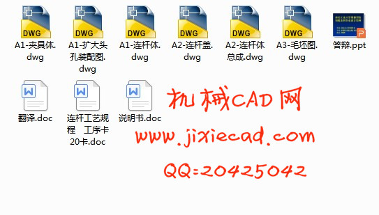
4.能熟练运用绘图软件绘制连杆及夹具图;
5.撰写设计说命书。
三、主要技术指标
1. 翻译文献1500-2000字;
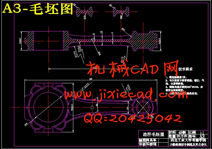
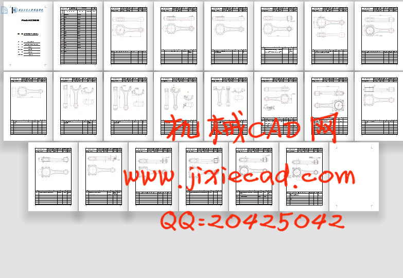
2. 完成连杆零件图毛坯图的绘制;
3. 完成连杆加工工艺规程的编制;
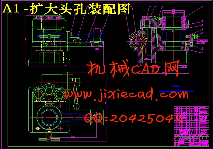
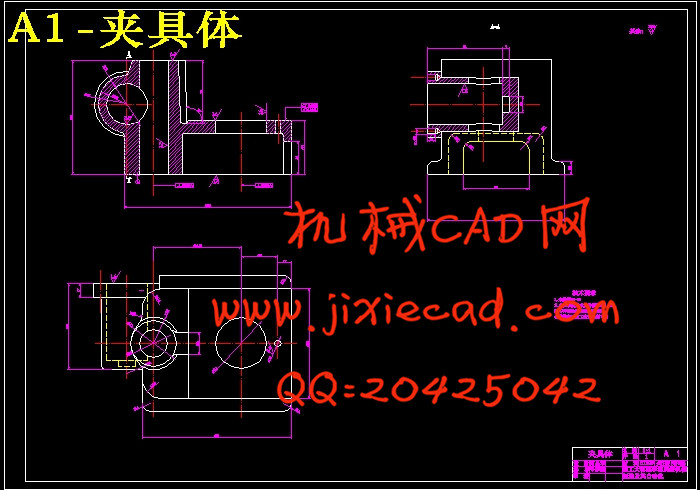
4. 完成扩孔夹具的设计;
5. 完成论文的撰写。
四、进度和要求
1.分析并绘制零件图 1 周
2.绘制毛坯图 1 周
3.设计工艺路线及编制工艺规程 4 周
4.设计工艺装备 3 周
5.编写设计说明书(论文) 2 周
6修改论文 1 周
7.制作文稿,准备答辩 1 周
8.毕业答辩 1 周
五、主要参考书及参考资料
[1] 阎光明,侯忠滨,张云鹏.现代制造工艺基础.西安:西北工业大学出
社,2007
[2] 朱耀祥,蒲林祥.现代夹具设计手册.北京:机械工业出版社,2011
[3] 杨叔子.机械加工工艺师手册. 北京:机械工业出版社,2010
[4] 王先逵.机械加工工艺手册. 北京:机械工业出版社,第二版,2003
[5] 陈宏钧.机械加工工艺设计员手册. 北京:机械工业出版社,2009
[6] 陈宏钧.机械加工工艺施工员手册. 北京:机械工业出版社,2008
[7] 邓文英.宋力宏.金属工艺学.北京:高等教育出版社,第五版,2008
[8] 赵家齐.北京:机械制造工艺学课程设计指导书,1994
[9] 李旦.王杰等.哈尔滨:机床专用夹具图册,第2版,2009
[10] 吴拓.北京:现代机床夹具设计,2009
[11] 陆剑中.孙家宁.金属切削原理与刀具.北京:机械工业出版社,第五
版,2009
摘要
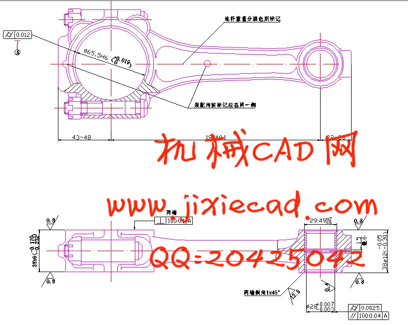
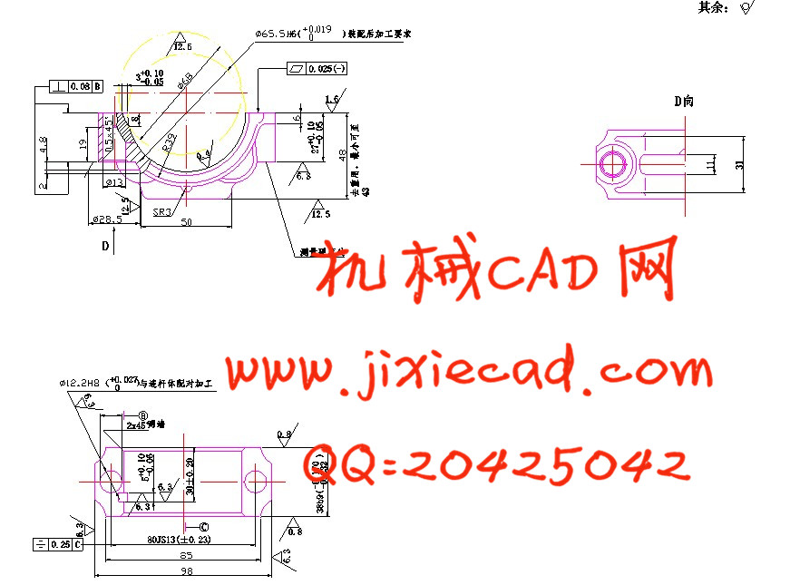
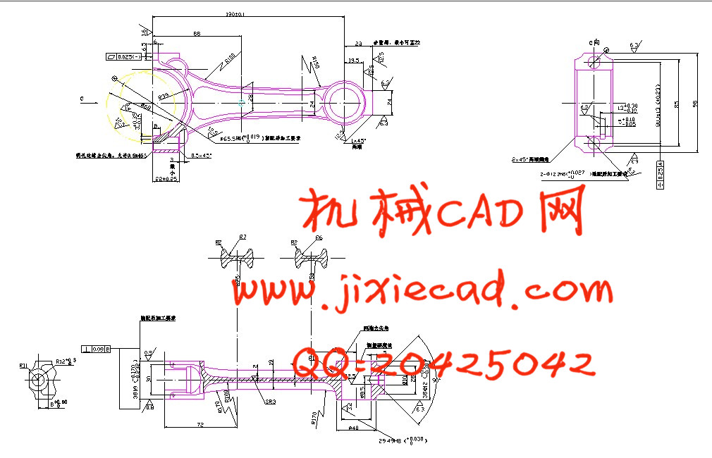
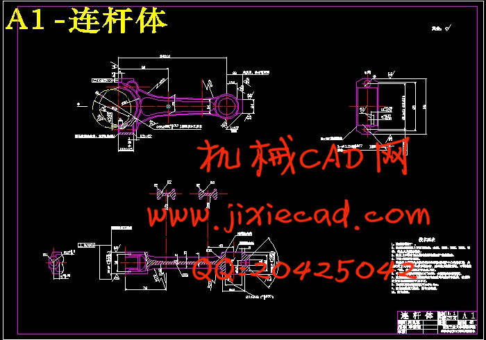
连杆是柴油机中的主要传动件之一,它连接着活塞和曲轴,其作用是将活塞的往复运动转变为曲轴的旋转运动,并作用在活塞上的力传给曲轴以输出功率。连杆在工作中,除承受燃烧室燃气产生的压力外,还要承受纵向和横向的惯性力。因此,连杆在一个复杂的应力状态下工作。它既受交变的拉压应力、又受弯曲应力。连杆的主要损坏形式是疲劳断裂和过量变形。通常疲劳断裂的部位是在连杆上的三个高应力区域。连杆的工作条件要求连杆具有较高的强度和抗疲劳性能;又要求具有足够的钢性和韧性。连杆的尺寸精度、形状精度以及位置精度的要求都很高,而连杆的刚性比较差,容易产生变形,因此在安排工艺过程时,就需要把各主要表面的粗精加工工序分开。逐步减少加工余量、切削力及内应力的作用,并修正加工后的变形,就能最后达到零件的技术要求。本文主要论述了连杆的加工工艺及其夹具设计。
关键词: 连杆,变形,加工工艺,夹具设计
ABSTRACT
一、题目
连杆工艺及扩孔夹具设计
二、指导思想和目的要求
1.本课题主要研究连杆的加工路线及扩孔夹具的设计;
2.在指导老师的指导下,能独立完成加工方案的拟定,编制工艺规程;
3.能熟练运用学过的理论知识,正确完成设计中的计算工作;
4.能熟练运用绘图软件绘制连杆及夹具图;
5.撰写设计说命书。
三、主要技术指标
1. 翻译文献1500-2000字;
2. 完成连杆零件图毛坯图的绘制;
3. 完成连杆加工工艺规程的编制;
4. 完成扩孔夹具的设计;
5. 完成论文的撰写。
四、进度和要求
1.分析并绘制零件图 1 周
2.绘制毛坯图 1 周
3.设计工艺路线及编制工艺规程 4 周
4.设计工艺装备 3 周
5.编写设计说明书(论文) 2 周
6修改论文 1 周
7.制作文稿,准备答辩 1 周
8.毕业答辩 1 周
五、主要参考书及参考资料
[1] 阎光明,侯忠滨,张云鹏.现代制造工艺基础.西安:西北工业大学出
社,2007
[2] 朱耀祥,蒲林祥.现代夹具设计手册.北京:机械工业出版社,2011
[3] 杨叔子.机械加工工艺师手册. 北京:机械工业出版社,2010
[4] 王先逵.机械加工工艺手册. 北京:机械工业出版社,第二版,2003
[5] 陈宏钧.机械加工工艺设计员手册. 北京:机械工业出版社,2009
[6] 陈宏钧.机械加工工艺施工员手册. 北京:机械工业出版社,2008
[7] 邓文英.宋力宏.金属工艺学.北京:高等教育出版社,第五版,2008
[8] 赵家齐.北京:机械制造工艺学课程设计指导书,1994
[9] 李旦.王杰等.哈尔滨:机床专用夹具图册,第2版,2009
[10] 吴拓.北京:现代机床夹具设计,2009
[11] 陆剑中.孙家宁.金属切削原理与刀具.北京:机械工业出版社,第五
版,2009
摘要
连杆是柴油机中的主要传动件之一,它连接着活塞和曲轴,其作用是将活塞的往复运动转变为曲轴的旋转运动,并作用在活塞上的力传给曲轴以输出功率。连杆在工作中,除承受燃烧室燃气产生的压力外,还要承受纵向和横向的惯性力。因此,连杆在一个复杂的应力状态下工作。它既受交变的拉压应力、又受弯曲应力。连杆的主要损坏形式是疲劳断裂和过量变形。通常疲劳断裂的部位是在连杆上的三个高应力区域。连杆的工作条件要求连杆具有较高的强度和抗疲劳性能;又要求具有足够的钢性和韧性。连杆的尺寸精度、形状精度以及位置精度的要求都很高,而连杆的刚性比较差,容易产生变形,因此在安排工艺过程时,就需要把各主要表面的粗精加工工序分开。逐步减少加工余量、切削力及内应力的作用,并修正加工后的变形,就能最后达到零件的技术要求。本文主要论述了连杆的加工工艺及其夹具设计。
关键词: 连杆,变形,加工工艺,夹具设计
ABSTRACT
The connecting rod is one of the main driving medium of diesel engine, it is connected to the piston and the crankshaft, it’s role is to the reciprocating piston movement into rotary movement of the crankshaft, and the of the force in the piston to the crankshaft to the output power. When working, the connecting rod not only support the pressure from the gas chamber, but also bear the vertical and horizontal inertia force. Therefore the connecting rod works in a complex environment .The main damage of the connecting rod is fatigue and excessive deformation . The working conditions of the connecting rod require it has higher strength and fatigue performance, and has enough rigidity and toughness. The precision of size, the precision of profile and the precision of position , of the connecting rod is demanded highly , and the rigidity of the connecting rod is not enough, easy to deform, so arranging the craft course, need to separate the each main and superficial thick finish machining process. Reduce the function of processing the surplus , cutting force and internal stress progressively , revise the deformation after processing, can reach the specification requirement for the part finally . This text expounds mainly the machining technology and the design of clamping device of the connecting rod.
Keyword: connecting rod ,deformation ,processing technology ,design of clamping device
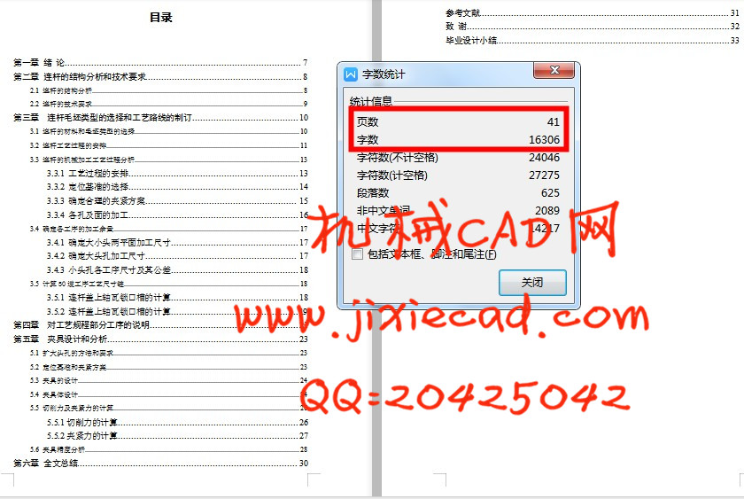
目录
第一章 绪 论 7Keyword: connecting rod ,deformation ,processing technology ,design of clamping device
目录
第二章 连杆的结构分析和技术要求 8
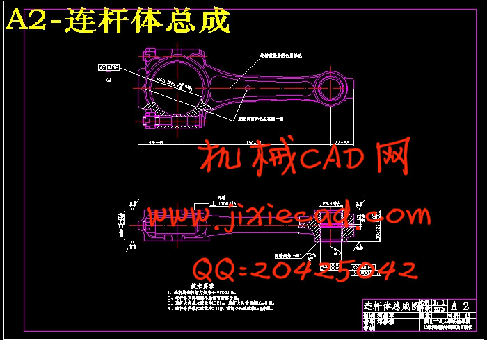
2.1 连杆的结构分析 8
2.2 连杆的技术要求 9
第三章 连杆毛坯类型的选择和工艺路线的制订 10
3.1 连杆的材料和毛坯类型的选择 10
3.2 连杆工艺过程的安排 11
3.3 连杆的机械加工工艺过程分析 13
3.3.1 工艺过程的安排 13
3.3.2 定位基准的选择 14
3.3.3 确定合理的夹紧方案 15
3.3.4 各孔及面的加工 16
3.4 确定各工序的加工余量 17
3.4.1 确定大小头两平面加工尺寸 17
3.4.2 确定大头孔加工尺寸 17
3.4.3 小头孔各工序尺寸及其公差 18
3.5 计算50道工序工艺尺寸链 18
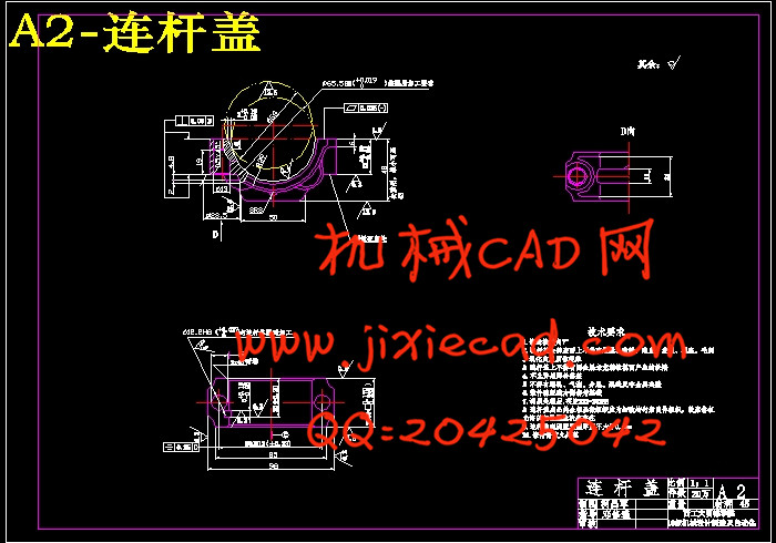
3.5.1 连杆盖上轴瓦锁口槽的计算 18
3.5.2 连杆盖上轴瓦锁口槽的计算 19
第四章 对工艺规程部分工序的说明 21
第五章 夹具设计和分析 23
5.1 扩大头孔的方法和要求 23
5.2 定位基准和夹紧方案 23
5.3 夹具的设计 24
5.4 夹具体设计 24
5.5 切削力及夹紧力的计算 26
5.5.1切削力的计算 26
5.5.2夹紧力的计算 27
5.6 夹具精度分析 28
第六章 全文总结 30
参考文献 31
致 谢 32
毕业设计小结 33