设计简介
摘 要
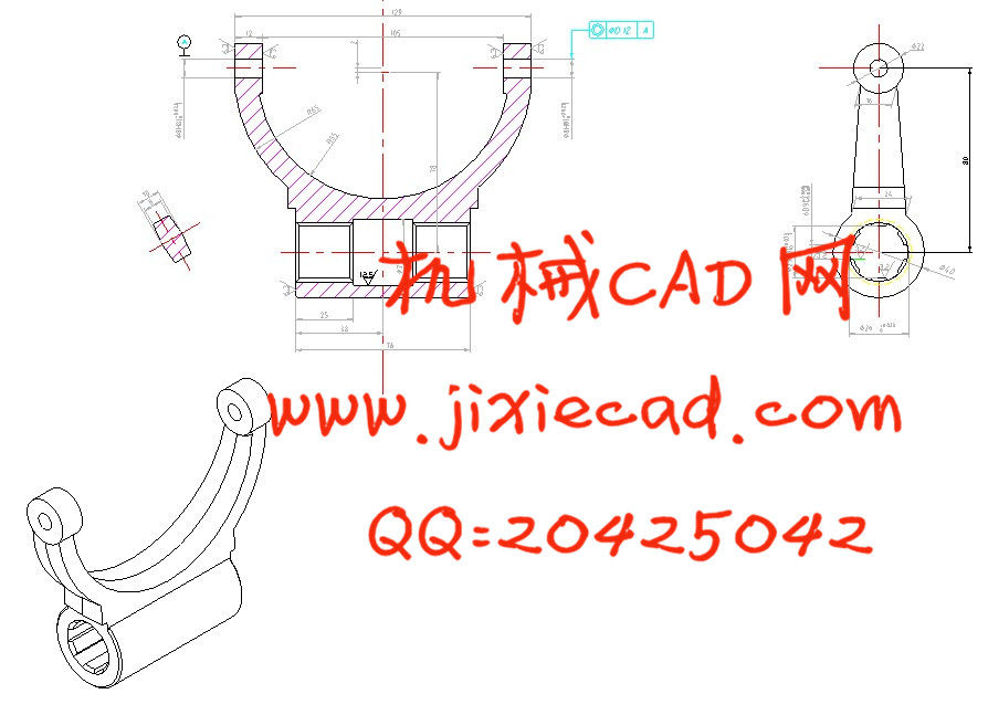
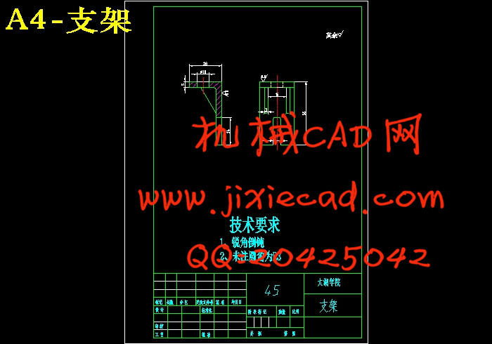
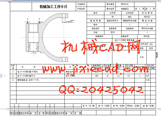
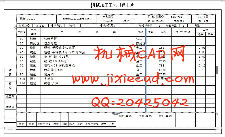
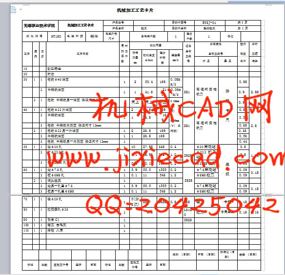
本次设计是对换挡拨叉零件的加工工艺规程及部分工序的专用夹具的设计。换挡拨叉零件的主要加工表面是平面及孔。由加工工艺原则可知,保证平面的加工精度要比保证孔的加工精度容易。所以本设计遵循先面后孔的原则。并将孔与平面的加工明确划分成粗加工和精加工阶段以保证加工精度。基准选择以换挡拨叉大外圆端面作为粗基准,以换挡拨叉大外圆端面与两个工艺孔作为精基准。主要加工工序安排是先以换挡拨叉大外圆端面互为基准加工出端面,再以端面定位加工出工艺孔。在后续工序中除个别工序外均用端面和工艺孔定位加工其他孔与平面。并对部分工序实现了气动夹紧。
关键词 拨叉;加工工艺;专用夹具;气动夹具
Abstract
The design is to decide process planning of shift fork parts and special clamp of part of a dedicated fixture. The main processing surface of the shift fork part is flat and the hole. Known by the principle of processing technology, we can easier ensure precision of the plane precision than the hole’s. Therefore, this design followed the principles, which machining the plane first. And a clear hole and surface processing is divided into roughing and finishing stages to ensure accuracy. The select of the rough base is a large cylindrical end, to shift fork end with two large cylindrical holes as a fine reference process. The first main processing operation to shift fork arrangement is a large cylindrical base machined end face each other, and then processed to face positioning technology holes. In addition to the follow-up processes are used outside of individual processes and process end processing of other hole’s location and plane. And designed a pneumatic fixture for one procession of the work-piece.
Key words: Fork; processing; special fixtures; pneumatic clamp
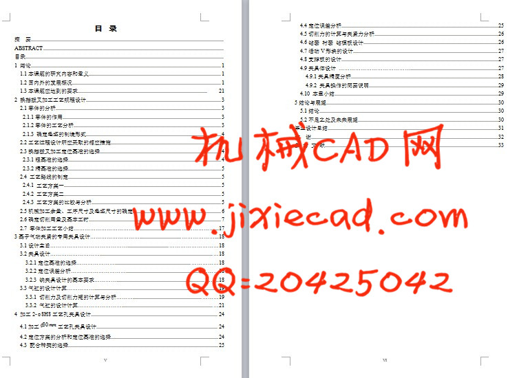
目 录
ABSTRACT
目录
1 绪论 1
1.1本课题的研究内容和意义 1
1.2国内外的发展概况 1
1.3本课题应达到的要求 21
2 换挡拨叉加工工艺规程设计 3
2.1零件的分析 3
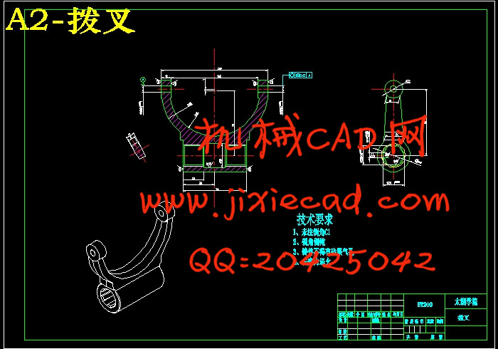
2.1.1零件的作用 3
2.1.2零件的工艺分析 3
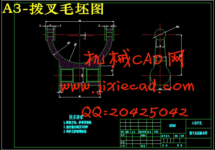
2.1.3 确定毛坯的制造形式 4
2.2工艺过程设计所应采取的相应措施 4
2.3换挡拨叉加工定位基准的选择 4
2.3.1粗基准的选择 4
2.3.2精基准的选择 5
2.4 工艺路线的制定 5
2.4.1 工艺方案一 5
2.4.2 工艺方案二 5
2.4.3 工艺方案的比较与分析 5
2.5机械加工余量、工序尺寸及毛坯尺寸的确定 6
2.6确定切削用量及基本工时 7
2.7 零件加工工艺小结……………………………… ………………...17
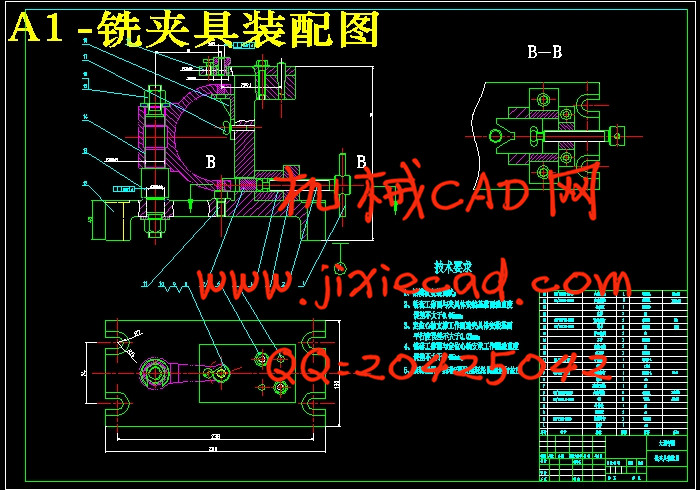
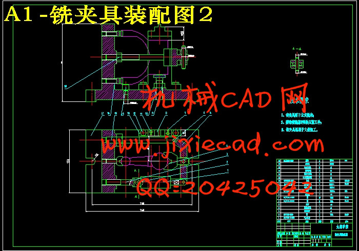
3基于气动夹紧的专用夹具设计……………………… ………………...18
3.1设计主旨…………………………………… ………………………18
3.2夹具设计……………………… …18
3.2.1定位基准的选择………………… ……………18
3.2.2定位误差分析………………………… ………18
3.2.3 铣夹具设计的基本要求………… ……..18
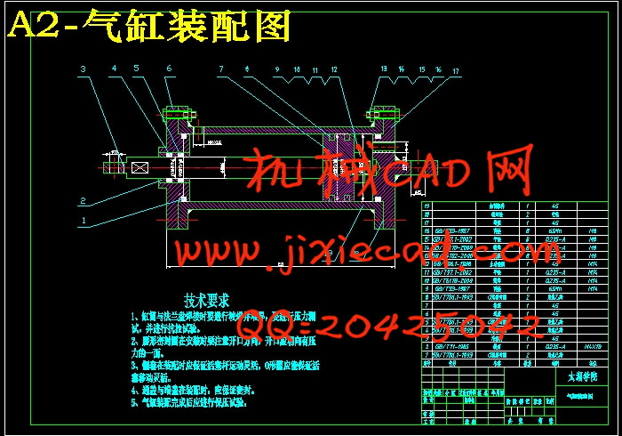
3.3气缸的设计计算…………… ..19
3.3.1 切削力及切削力矩的计算与分析……… ………19
3.3.2 气缸的设计计算…………………… …21
4 加工2-φ8H8工艺孔夹具设计 24
4.1加工
4.2定位方案的分析和定位基准的选择 24
4.3 配合种类的选择 25
4.4定位误差分析 25
4.5切削力的计算与夹紧力分析 26
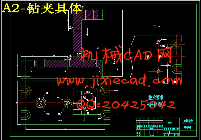
4.6钻套 衬套 钻模板设计 26
4.7活动V形块的设计 27
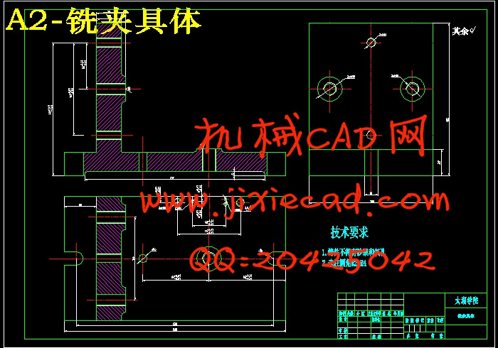
4.8支撑板的设计 27
4.9夹具体设计 ………………………………… .27
4.9.1夹具精度分析 28
4.9.2 夹具操作的简要说明 29
4.10 本章小结 29
5结论与展望 30
5.1结论 30
5.2不足之处及未来展望 30
毕业设计总结 31
致 谢 32
参 考 文 献 33