设计简介
摘 要
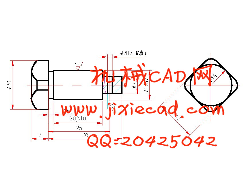
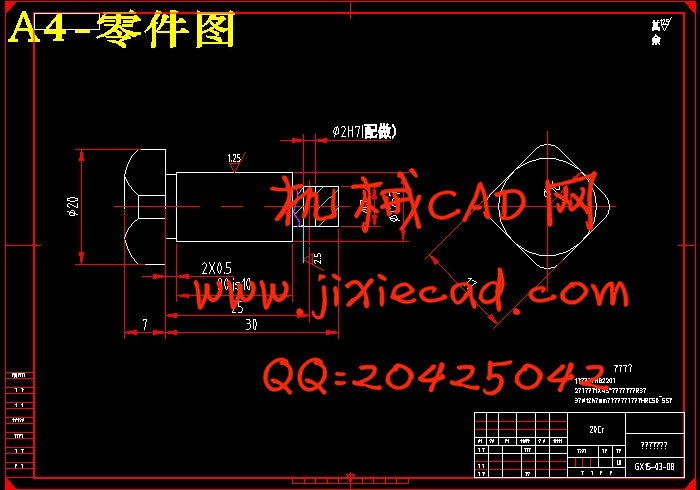
本文首先对方头小轴零件进行分析,通过对方头小轴进行研究和分析,描述了它的毛坯制造形式、机械加工余量、基准选择、工序尺寸和毛坯尺寸的确定,以及切削用量和工时的计算和加工刀具的设计等相关内容。
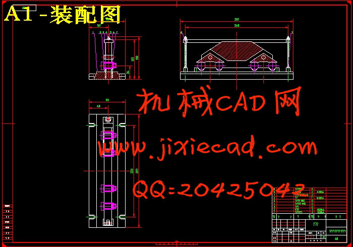
在这次毕业设计中,根据课题所给的零件图、技术要求,通过查阅相关资料和书籍,了解和掌握了的机械加工工艺和编程的一般方法和步骤,并运用这些方法和步骤进行了方头小轴铣方头扁位夹具设计,整个铣扁位夹具的设计的指导思想“简便、高效、经济”。力求生产处符合要求的产品。
关键词:方头小轴;加工余量;铣扁位夹具;经济
ABSTRACT
This design is a lather to become soon an appropriation for inside pulling out fork spare parts processing craft rules distance and some work prefaces tongs design.This pull out the construction of the fork spare parts than for complicacy, its the place that process is a peaceful in bore primarily.This design processes after processing first the bore.Process with flat surface the clear and definite dividing the line the bore the coarseness processes to process with the nicety the stage to guarantee their process the precise degree.本文首先对方头小轴零件进行分析,通过对方头小轴进行研究和分析,描述了它的毛坯制造形式、机械加工余量、基准选择、工序尺寸和毛坯尺寸的确定,以及切削用量和工时的计算和加工刀具的设计等相关内容。
在这次毕业设计中,根据课题所给的零件图、技术要求,通过查阅相关资料和书籍,了解和掌握了的机械加工工艺和编程的一般方法和步骤,并运用这些方法和步骤进行了方头小轴铣方头扁位夹具设计,整个铣扁位夹具的设计的指导思想“简便、高效、经济”。力求生产处符合要求的产品。
关键词:方头小轴;加工余量;铣扁位夹具;经济
ABSTRACT
The basis of automation. Use of machine tools, need a large number of skilled personnel of modern numerical control technology. The application of numerical control technology not only bring revolutionary change to traditional manufacturing industry, manufacturing industry has become a symbol of industrialization, and with the continuous development of numerical control technology and application field expands, it to the national economy and people′s livelihood some important industry plays a more and more important role in the development.
KEYWORDS:fixture multi-function; Die forging links; Group technology;clipping tight
目录
摘要 I
ABSTRACT II
第一章 绪论 1
1.1课题背景 1
1.2夹具的发展史 1
1.3 小结 1
第二章 方头小轴的加工工艺规程设计 2
2.1零件的分析 2
2.1.1零件的作用 3
2.1.2零件的工艺分析 4
2.2确定生产类型 8
2.3确定毛坯 12
2.3.1确定毛坯种类 13
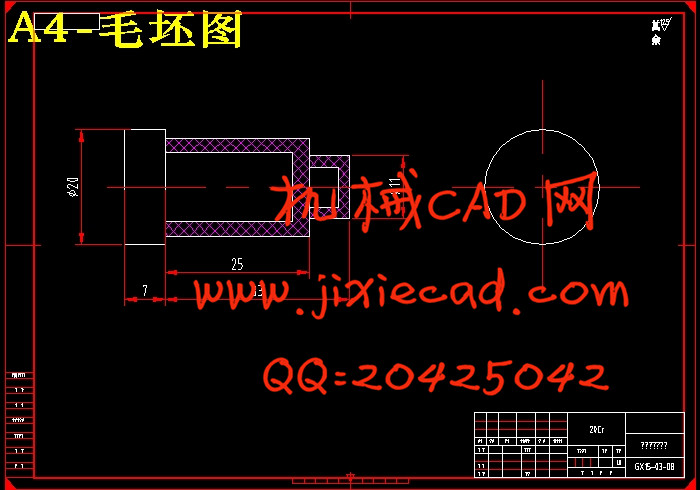
2.3.2确定零件加工余量及形状 15
2.3.3绘制零件毛坯图 17
2.4工艺规程设计 18
2.4.1选择定位基准 18
2.4.2制定工艺路线 18
2.4.3选择加工设备和工艺设备 19
2.4.4机械加工余量、工序尺寸及公差的确定 19
2.5确定切削用量及基本工时 19
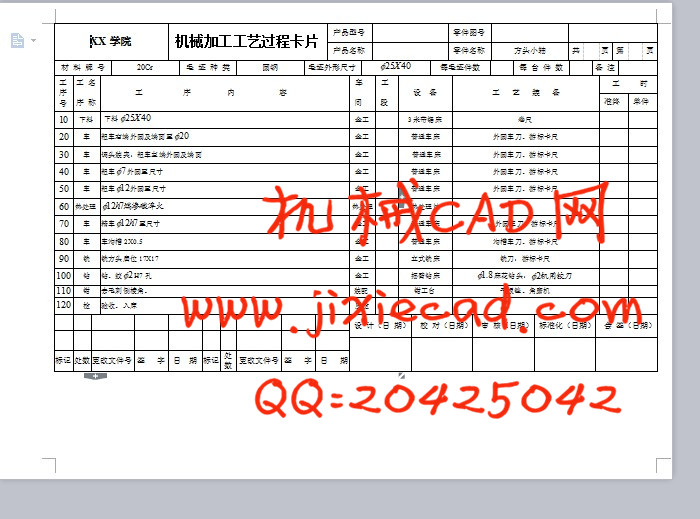
2.5.1工序20:粗车右端外圆及端面至
2.5.2工序30:调头装夹,粗车左端外圆及端面 21
2.5.3工序40:粗车
2.5.4工序50:粗车
2.5.5工序70:精车
2.5.6工序80:车沟槽2X0.5 23
2.5.7工序90:铣方头扁位17X17 23
2.5.8工序100:钻、绞
第三章 专用夹具设计 24
3.1铣夹具设计 25
3.1.1问题的提出 25
3.1.2夹具的设计 26
第四章 刀具设计 26
结论 28
参考文献 29
致谢 3