设计简介
摘要
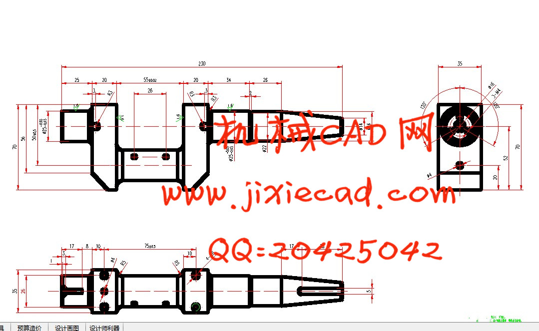
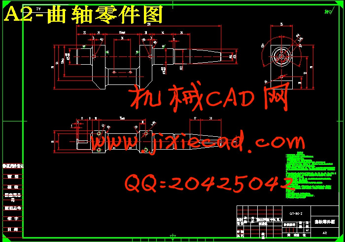
本篇设计是基于UG的11ZA-1.58型空气压缩机铣曲轴键槽夹具设计。曲轴零件的主要加工表面是主轴颈外圆及连杆体上下,左右表面,油孔,以及螺纹孔和键槽的加工。一般来说,保证平面的加工精度与保证轴系的加工精度相比,保证平面的加工精度比较容易。键槽加工都是选用专用铣床夹具,夹紧方式一般选用手动夹紧,夹紧可靠。因此生产效率较高。能够满足设计要求。
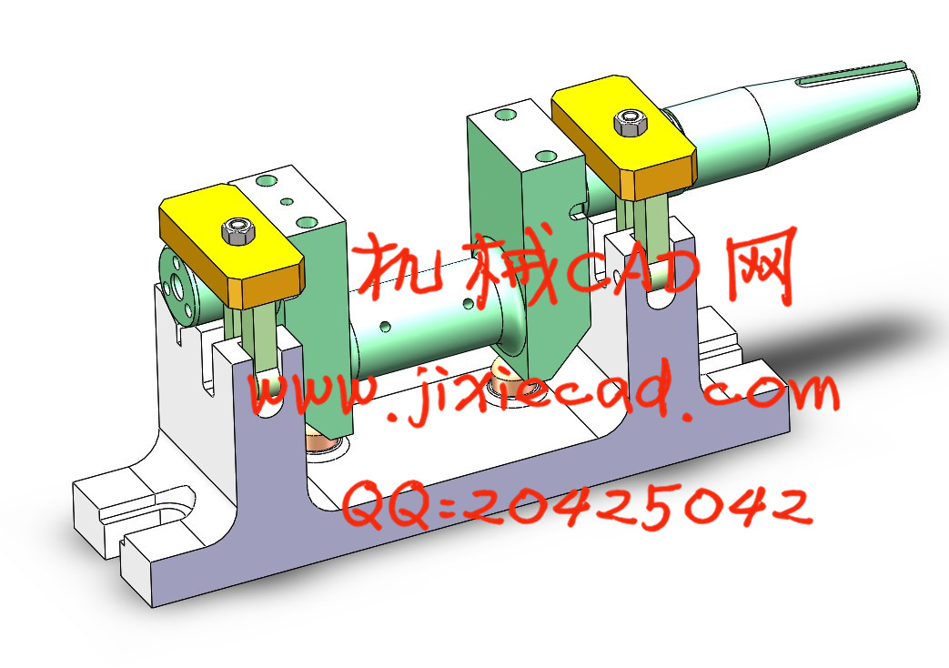
文章的重点在于对空气压缩机曲轴的工艺性和力学性能分析,对加工工艺进行合理分析,选择确定合理的毛坯、加工方式、高效设计、省力的夹具,经过实践证明,最终加工出合格的曲轴零件。本文的创新之处在于用UG软件绘制铣键槽夹具的三维装配图和零件图,它的主要特点是三维建模,使夹具的装配顺序及可视效果都一目了然。
关键词:曲轴加工表面;铣槽夹具;三维建模
The emphasis of this paper is to analyze the process and mechanical properties of the air compressor crankshaft, and to select the reasonable blank, processing method, high efficiency design and saving fixture. The innovation of this paper lies in keyway milling fixture 3D assembly drawings and part drawings drawn by using UG software, its main characteristic is 3D modeling, the fixture assembly sequence and visual effects are clear.
Key words: keyway;right surface;milling fixture; sequence
工序130粗铣、精铣连杆上、下及前、后端 22
工序140磨削主轴颈右端 23
工序150磨削主轴颈左端 24
4.2时间定额计算及生产安排 24
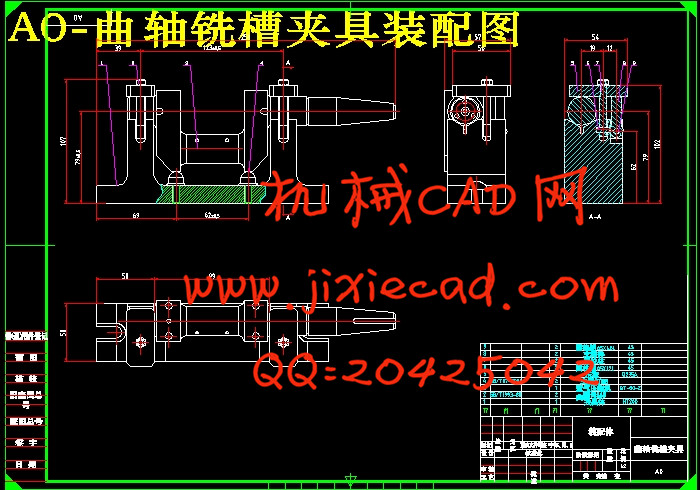
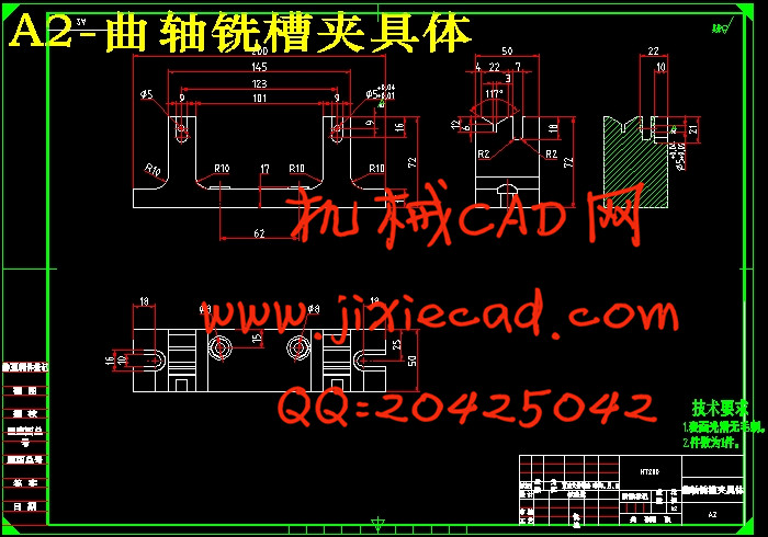
第五章 曲轴铣键槽夹具设计 25
5.1铣键槽夹具设计 26
5.2定位基准的选择 28
5.3切削力的计算与夹紧力分析 28
5.4定位误差的分析 31
5.5夹具设计简要操作说明 31
第六章 UG软件在机械设计中的应用 32
结 论 33
参考文献 34
致 谢 35
本篇设计是基于UG的11ZA-1.58型空气压缩机铣曲轴键槽夹具设计。曲轴零件的主要加工表面是主轴颈外圆及连杆体上下,左右表面,油孔,以及螺纹孔和键槽的加工。一般来说,保证平面的加工精度与保证轴系的加工精度相比,保证平面的加工精度比较容易。键槽加工都是选用专用铣床夹具,夹紧方式一般选用手动夹紧,夹紧可靠。因此生产效率较高。能够满足设计要求。
文章的重点在于对空气压缩机曲轴的工艺性和力学性能分析,对加工工艺进行合理分析,选择确定合理的毛坯、加工方式、高效设计、省力的夹具,经过实践证明,最终加工出合格的曲轴零件。本文的创新之处在于用UG软件绘制铣键槽夹具的三维装配图和零件图,它的主要特点是三维建模,使夹具的装配顺序及可视效果都一目了然。
关键词:曲轴加工表面;铣槽夹具;三维建模
Abstract
keyway fixture based on. Crankshaft parts of the main surface is on the main shaft neck of the outer circle of the connecting rod and the body, left and right surface, oil hole, and screw hole and keyway processing. In general, to ensure the accuracy of the machining process and the accuracy of the system to ensure that the accuracy of the plane is relatively easy to ensure the accuracy of the plane. Keyseating is the special milling fixture, the clamping way generally manual clamping, clamping reliable. So the production efficiency is higher. Be able to meet the design requirements.The emphasis of this paper is to analyze the process and mechanical properties of the air compressor crankshaft, and to select the reasonable blank, processing method, high efficiency design and saving fixture. The innovation of this paper lies in keyway milling fixture 3D assembly drawings and part drawings drawn by using UG software, its main characteristic is 3D modeling, the fixture assembly sequence and visual effects are clear.
Key words: keyway;right surface;milling fixture; sequence
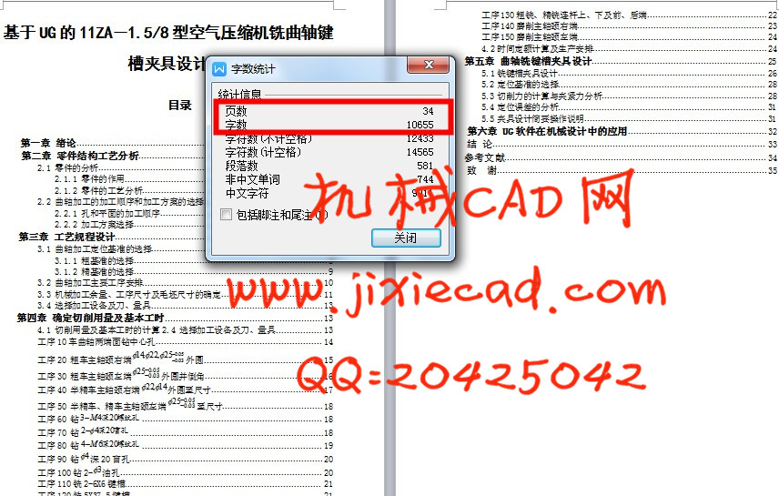
基于UG的11ZA-1.5/8型空气压缩机铣曲轴键槽夹具设计
目录
第一章 绪论 1
第二章 零件结构工艺分析 1
2.1 零件的分析 1
2.1.1 零件的作用 2
2.1.2 零件的工艺分析 3
2.2 曲轴加工的加工顺序和加工方案的选择 3
2.2.1 孔和平面的加工顺序 5
2.2.2 加工方案选择 5
第三章 工艺规程设计 6
3.1 曲轴加工定位基准的选择 7
3.1.1 粗基准的选择 8
3.1.2 精基准的选择 9
3.2 曲轴加工主要工序安排 10
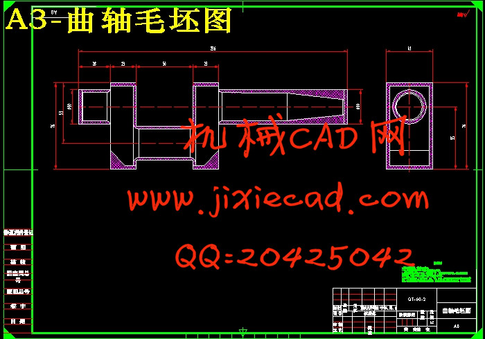
3.3 机械加工余量、工序尺寸及毛坯尺寸的确定 11
3.4 选择加工设备及刀、量具 13
第四章 确定切削用量及基本工时 13
4.1 切削用量及基本工时的计算2.4 选择加工设备及刀、量具 13
工序10车曲轴两端面钻中心孔 14
工序20 粗车主轴颈右端 外圆 15
外圆 15
工序30 粗车主轴颈左端 外圆并倒角 16
工序40 半精车主轴颈右端 外圆至尺寸 17
工序50 半精车、精车主轴颈左端 至尺寸 18
工序60 钻 18
18
工序70 钻 18
18
工序80 钻 19
19
工序90 钻 深20盲孔 20
工序100钻2- 油孔 20
油孔 20
工序110铣2-6X6键槽 21
工序120铣5X37.5键槽 21
目录
第一章 绪论 1
第二章 零件结构工艺分析 1
2.1 零件的分析 1
2.1.1 零件的作用 2
2.1.2 零件的工艺分析 3
2.2 曲轴加工的加工顺序和加工方案的选择 3
2.2.1 孔和平面的加工顺序 5
2.2.2 加工方案选择 5
第三章 工艺规程设计 6
3.1 曲轴加工定位基准的选择 7
3.1.1 粗基准的选择 8
3.1.2 精基准的选择 9
3.2 曲轴加工主要工序安排 10
3.3 机械加工余量、工序尺寸及毛坯尺寸的确定 11
3.4 选择加工设备及刀、量具 13
第四章 确定切削用量及基本工时 13
4.1 切削用量及基本工时的计算2.4 选择加工设备及刀、量具 13
工序10车曲轴两端面钻中心孔 14
工序20 粗车主轴颈右端
工序30 粗车主轴颈左端
工序40 半精车主轴颈右端
工序50 半精车、精车主轴颈左端
工序60 钻
工序70 钻
工序80 钻
工序90 钻
工序100钻2-
工序110铣2-6X6键槽 21
工序120铣5X37.5键槽 21
工序130粗铣、精铣连杆上、下及前、后端 22
工序140磨削主轴颈右端 23
工序150磨削主轴颈左端 24
4.2时间定额计算及生产安排 24
第五章 曲轴铣键槽夹具设计 25
5.1铣键槽夹具设计 26
5.2定位基准的选择 28
5.3切削力的计算与夹紧力分析 28
5.4定位误差的分析 31
5.5夹具设计简要操作说明 31
第六章 UG软件在机械设计中的应用 32
结 论 33
参考文献 34
致 谢 35