设计简介
摘要
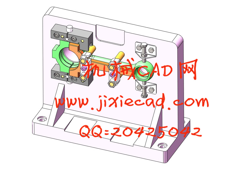
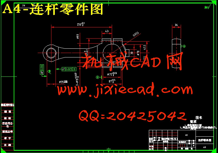
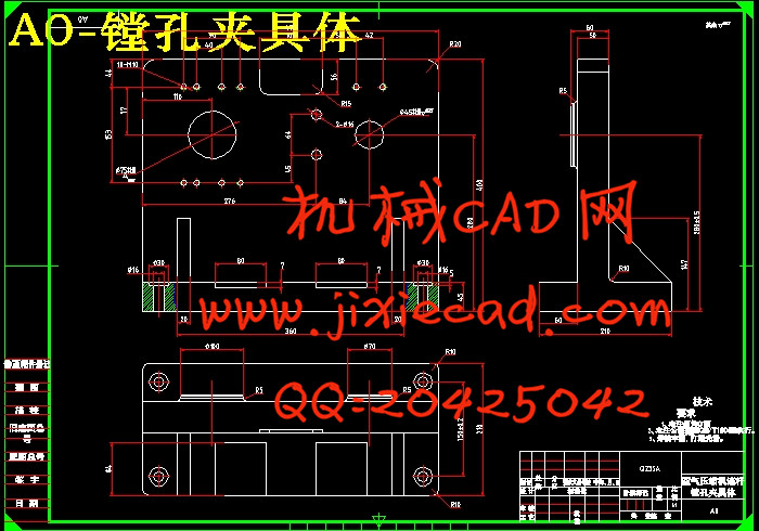
本篇设计是基于UG的11ZA-1.58型空气压缩机连杆精镗大、小头孔夹具设计。连杆零件的主要加工位置是 、
、 内孔的加工及连杆上下,左右表面,油孔,以及
 直孔的加工。一般来说,保证平面的加工精度与保证轴系的加工精度相比,保证平面的加工精度比较容易。精镗大、小头孔加工都是选用专用镗床夹具,夹紧方式一般选用手动夹紧,夹紧可靠。因此生产效率较高。能够满足设计要求。
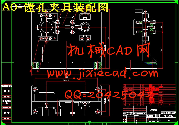
文章的重点在于对空气压缩机连杆的工艺性和力学性能分析,对加工工艺进行合理分析,选择确定合理的毛坯、加工方式、高效设计、省力的夹具,经过实践证明,最终加工出合格的连杆零件。本文的创新之处在于用UG软件绘制精镗大、小头孔夹具的三维装配图和零件图,它的主要特点是三维建模,使夹具的装配顺序及可视效果都一目了然。
关键词:连杆;精镗;夹具;装配图
The focus of the article is on the air compressor connecting rod, the processing and mechanical properties analysis on the process of rational analysis, to determine the reasonable blank, processing, efficient design, labor saving fixture. Through practice proved that ultimately produce a qualified connecting parts. The innovation of this paper lies in using UG software rendering fine boring, small head hole fixture 3D assembly drawing and parts drawing. Its main characteristic is 3D modeling, the fixture assembly sequence and visual effects are clear.
Key words: keyway;right surface;milling fixture; sequence hining accuracy of the system is relatively easy. Fine boring, small hole machining is the special boring machine fixture, the clamping way generally manual clamping, clamping reliable. Therefore, the production efficiency is high. Can meet the design requirements.
The focus of the article is on the air compressor connecting rod, the processing and mechanical properties analysis on the process of rational analysis, to determine the reasonable blank, processing, efficient design, labor saving fixture. Through practice proved that ultimately produce a qualified connecting parts. The innovation of this paper lies in using UG software rendering fine boring, small head hole fixture 3D assembly drawing and parts drawing. Its main characteristic is 3D modeling, the fixture assembly sequence and visual effects are clear.
Key words: keyway;right surface;milling fixture; sequence
目录
第一章 绪论 1
第二章 零件的分析 1
2.1 零件的作用 2
2.2 零件的工艺分析 3
2.3 连杆加工的加工顺序和加工方案的选择 4
2.3.1 孔和平面的加工顺序 5
2.3.2 加工方案选择 5
第三章 工艺规程设计 6
3.1 连杆加工定位基准的选择 7
3.1.1 粗基准的选择 8
3.1.2 精基准的选择 9
3.2 连杆加工主要工序安排 10
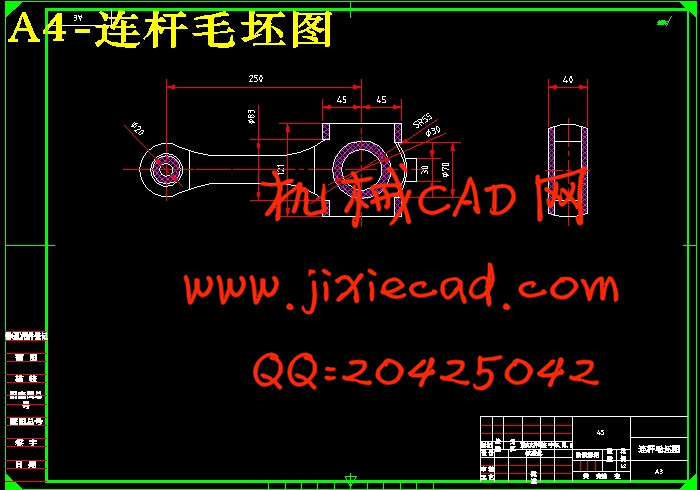
3.3 机械加工余量、工序尺寸及毛坯尺寸的确定 10
3.4 选择加工设备及刀、量具 10
第四章 确定切削用量及基本工时 10
4.1 切削用量及基本工时的计算 11
工序1划线 11
工序2钻中心孔 11
工序3 两头顶住,四爪夹小头,车大头各外圆,端面及球面 12
工序4 两头顶住,四爪夹大头,粗、精车小头球面和杆部外圆及各圆弧 12
工序5 铣两平面至厚 13
13
工序6 钻小头孔至 13
13
工序7 粗镗大、小头孔至 、
、 13
13
工序8 铣杆部150处平面及R37.5圆弧面 14
工序9 铣杆部及R37.5宽20的槽 14
工序10 插大头杆盖止口 14
工序11粗磨平面至厚 14
14
工序12铣开对开面 15
工序13铣杆体对开面至 15
15
工序14铣除杆体中心孔多余部分至球面线 16
工序15铣杆盖 搭子两侧面至厚10 17
工序16钻 直孔,扩孔至
 铰孔至
铰孔至 18
18
工序17半精镗大、小头孔至 、
、 19
19
工序18钻大、小头孔倒角至尺寸 20
工序19磨平面至厚度 20
20
工序20精镗大、小头孔至尺寸 21
工序21精镗铜套内孔至尺寸 21
第五章 镗孔夹具设计 22
5.1定位基准的选择 24
5.2定位元件的设计 25
5.3切削力及夹紧力的计算 25
5.4夹紧装置设计 26
5.5夹具误差分析和计算 27
第六章 UG软件在机械设计中的应用 27
结 论 28
参考文献 29
致 谢 30
本篇设计是基于UG的11ZA-1.58型空气压缩机连杆精镗大、小头孔夹具设计。连杆零件的主要加工位置是
文章的重点在于对空气压缩机连杆的工艺性和力学性能分析,对加工工艺进行合理分析,选择确定合理的毛坯、加工方式、高效设计、省力的夹具,经过实践证明,最终加工出合格的连杆零件。本文的创新之处在于用UG软件绘制精镗大、小头孔夹具的三维装配图和零件图,它的主要特点是三维建模,使夹具的装配顺序及可视效果都一目了然。
关键词:连杆;精镗;夹具;装配图
Abstract
This design is UG 11ZA 1.58 type air compressor connecting rod small hole boring fixture design based on. The main machining position of connecting rod parts is, the processing of inner hole and the connecting rod of the connecting rod, the left and right surface, the oil hole, and the processing of the straight hole. Generally speaking, the machining accuracy of the plane is guaranteed to ensure the machining accuracy of the system is relatively easy. Fine boring, small hole machining is the special boring machine fixture, the clamping way generally manual clamping, clamping reliable. Therefore, the production efficiency is high. Can meet the design requirements.The focus of the article is on the air compressor connecting rod, the processing and mechanical properties analysis on the process of rational analysis, to determine the reasonable blank, processing, efficient design, labor saving fixture. Through practice proved that ultimately produce a qualified connecting parts. The innovation of this paper lies in using UG software rendering fine boring, small head hole fixture 3D assembly drawing and parts drawing. Its main characteristic is 3D modeling, the fixture assembly sequence and visual effects are clear.
Key words: keyway;right surface;milling fixture; sequence hining accuracy of the system is relatively easy. Fine boring, small hole machining is the special boring machine fixture, the clamping way generally manual clamping, clamping reliable. Therefore, the production efficiency is high. Can meet the design requirements.
The focus of the article is on the air compressor connecting rod, the processing and mechanical properties analysis on the process of rational analysis, to determine the reasonable blank, processing, efficient design, labor saving fixture. Through practice proved that ultimately produce a qualified connecting parts. The innovation of this paper lies in using UG software rendering fine boring, small head hole fixture 3D assembly drawing and parts drawing. Its main characteristic is 3D modeling, the fixture assembly sequence and visual effects are clear.
Key words: keyway;right surface;milling fixture; sequence
目录
第一章 绪论 1
第二章 零件的分析 1
2.1 零件的作用 2
2.2 零件的工艺分析 3
2.3 连杆加工的加工顺序和加工方案的选择 4
2.3.1 孔和平面的加工顺序 5
2.3.2 加工方案选择 5
第三章 工艺规程设计 6
3.1 连杆加工定位基准的选择 7
3.1.1 粗基准的选择 8
3.1.2 精基准的选择 9
3.2 连杆加工主要工序安排 10
3.3 机械加工余量、工序尺寸及毛坯尺寸的确定 10
3.4 选择加工设备及刀、量具 10
第四章 确定切削用量及基本工时 10
4.1 切削用量及基本工时的计算 11
工序1划线 11
工序2钻中心孔 11
工序3 两头顶住,四爪夹小头,车大头各外圆,端面及球面 12
工序4 两头顶住,四爪夹大头,粗、精车小头球面和杆部外圆及各圆弧 12
工序5 铣两平面至厚
工序6 钻小头孔至
工序7 粗镗大、小头孔至
工序8 铣杆部150处平面及R37.5圆弧面 14
工序9 铣杆部及R37.5宽20的槽 14
工序10 插大头杆盖止口 14
工序11粗磨平面至厚
工序12铣开对开面 15
工序13铣杆体对开面至
工序14铣除杆体中心孔多余部分至球面线 16
工序15铣杆盖
工序16钻
工序17半精镗大、小头孔至
工序18钻大、小头孔倒角至尺寸 20
工序19磨平面至厚度
工序20精镗大、小头孔至尺寸 21
工序21精镗铜套内孔至尺寸 21
第五章 镗孔夹具设计 22
5.1定位基准的选择 24
5.2定位元件的设计 25
5.3切削力及夹紧力的计算 25
5.4夹紧装置设计 26
5.5夹具误差分析和计算 27
第六章 UG软件在机械设计中的应用 27
结 论 28
参考文献 29
致 谢 30