设计简介
摘要:本设计介绍了495曲轴零件工艺、钻润滑油孔夹具及专用机床的设计,其中包含了零件加工工艺的确定,设计中首先要了解工件的加工工艺路线及工序的计算,确定钻润滑油孔主轴的直径,初步选用电机型号及机床各部分部件。编制三图一卡(被加工零件工序图,加工示意图,机床联系尺寸图,机床生产率计算卡)。在多轴箱设计中,确定传动系统,计算主轴坐标,传动部件的校核及主轴箱的总图绘制。
本设计将钻孔工装实现了通用化,从而降低了机器成本,而且节省了加工时间,提高了工作生产效率。
关键词: 曲轴;专业机床;多轴箱;工装
Abstract:The design on the Lidao Biansuchilun Box axlebox more than the design, which includes parts fthe processing technology of identification, design is first necessary to understand the workpiece intheprocessing line and process of calculation to determine Tapping the spindle diameter, the initial choice ofmotor Model and some parts of the machine. Figure 1 of the three cards (the processing parts process map,diagram processing, machine tools Contact size map, machine tool productivity calculation card). Inmulti-axle box design, drive system established to calculate coordinates spindle, transmission parts of the spindlebox and check the total mapping.
This design will be drilling, tapping combination of the two as one and reduce the cost of machinery, processing and save time, improve the work efficiency of production.
Key words:Machine manufacture,;Crankshaft,;Processing craft, Fixture;tool box
目 录
绪论 1
1. 组合机床概述 1
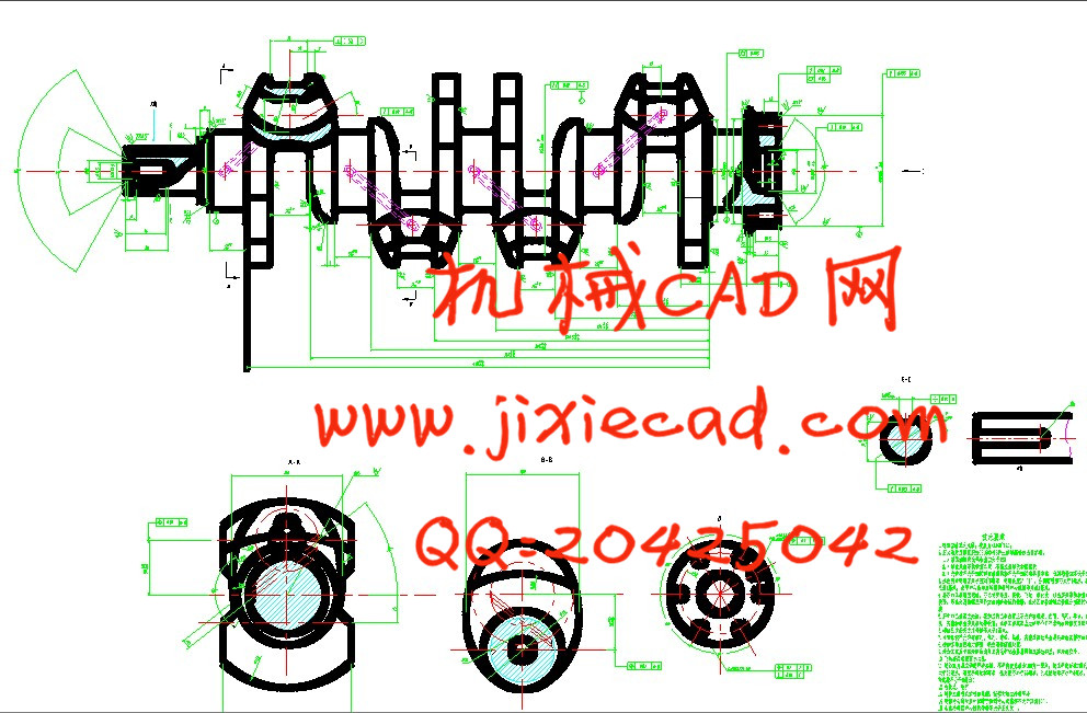
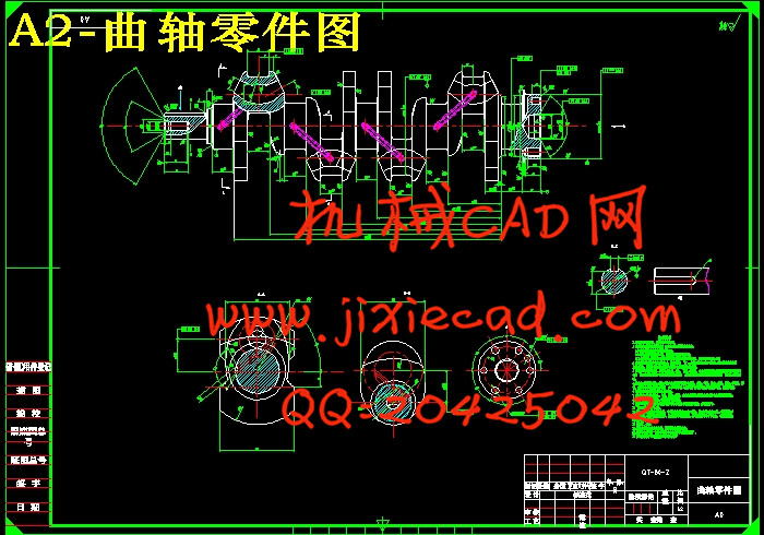
2. 495曲轴零件工艺分析 5
2.1 被加工零件的功用 5
2.2 编制工艺规程及分析 5
2.2.1 被加工零件的技术要求 5
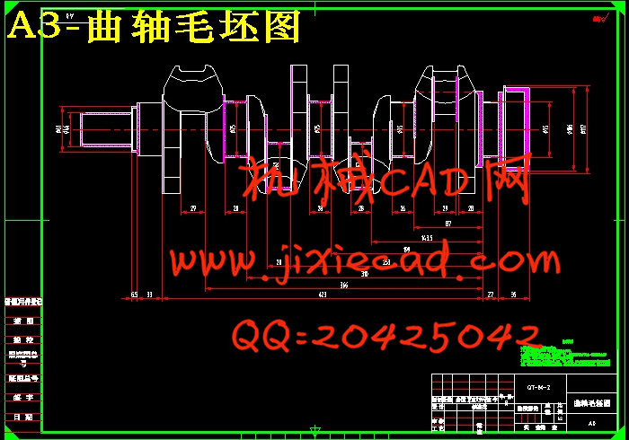
2.2.2 毛坯的选用 6
2.3 零件加工工艺路线的拟定 7
2.3.1 定位基准的选择 8
2.3.1.1 粗基准的选择 8
2.3.1.2 精基准的选择 8
2.4 制定工艺路线 10
2.5 零件技术条件分析 10
2.6 初步拟定工艺规程 10
2.7 所用设备及工艺装备 10
2.8 切削用量的确定 10
3. 钻孔组合机床的结构设计 11
3.1 组合机床的配置形式的选择 11
3.2 动力部件的选择 11
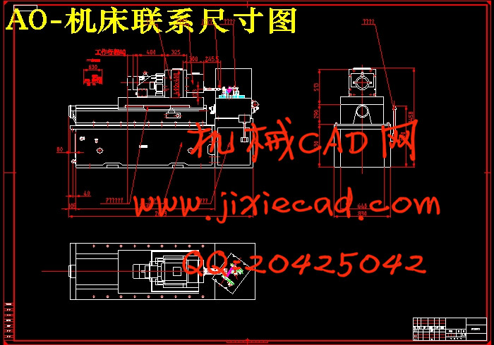
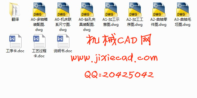
4. 绘制“三图一卡” 16
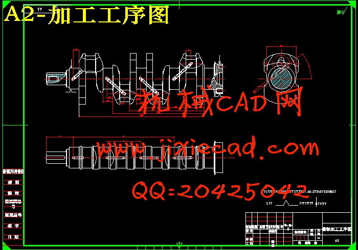
4.1 绘制被加工零件工序图 16
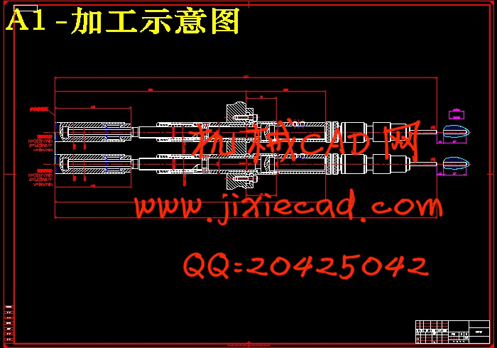
4.2 绘制被加工零件加工示意图 16
4.3 机床联系尺寸图的绘制 18
4.4 专用机床生产率计算卡的编制 18
4.4.1 生产率的计算 18
4.4.2 编写生产率计算卡 20
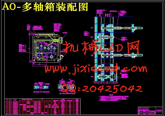
5. 组合机床钻润滑油孔多轴箱设计 21
5.1 钻孔概述 21
5.2.1 内容及注意事项 21
5.2.2 主轴外伸尺寸及切削用量 22
5.3 主轴齿轮的确定及计算 22
5.3.1 主轴形式和直径,齿轮模数的确定 22
5.3.2 多轴箱所需动力计算 23
5.4 多轴箱的传动设计 24
5.4.1 对多轴箱的传动系统的一般要求 25
5.4.2 拟订多轴箱传动系统的方法 25
5.5 对传动零件进行校核 25
5.5.1 轴的挍核 26
5.5.2 齿轮的挍核 27
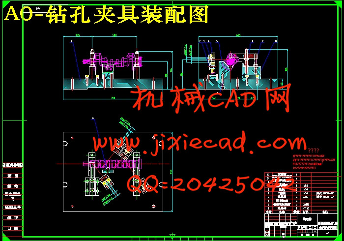
5.6 钻润滑油孔夹具的设计 28
5.6.1 钻孔靠模机构及卡头 29
5.6.2 钻孔装置 30
5.6.3 钻孔行程的控制 30
6. 结论 31
附录 32
参考文献 33
致谢 34