设计简介
摘 要
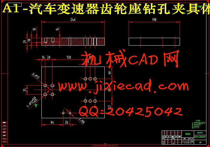
本次设计的主要内容是汽车变速器齿轮座工艺及工装夹具的设计。齿轮座主要是与齿轮、轴承等零件配对使用,其主要加工表面及控制位置为【关键词】汽车变速器齿轮座、工艺、定位
Abstract
This paper is abute automated devices that can mimic the human hand and arm movements to do something,aslo can according to a fixed procedure to moving objects or control tools. It can replace the heavy labor in order to achieve the productionmechanization
  and automation, and can work in dangerous working environments to protect the personal safety,
 Therefore widely
 used in machine building,metallurgy, electronics, light industry and atomic energy sectors.This article is mainly
  of the pneumatic manipulator the overall design,
  and pneumaticdesign. This mechanism of manipulator includes cylinders and claws and connectors
  parts, it can move according to the due track on the movement ofgrabbing, carrying and unloading. The pneumatic part of the design is primarily to choose the right valves and design a reasonable pneumatic control loop, by controlling and regulating pressure, flow and direction of the compressed air to make it get the necessary strength, speed and changed the direction of movement in the prescribed procedure work.It can replace the heavy labor in order to achieve the production mechanization and automation, and can work in dangerous working environments to protect the personal safety, Therefore widely used in machine building, metallurgy, electronics, light industry and atomic .
【关键词】pneumatic manipulator 、cylinder、pneumatic loop
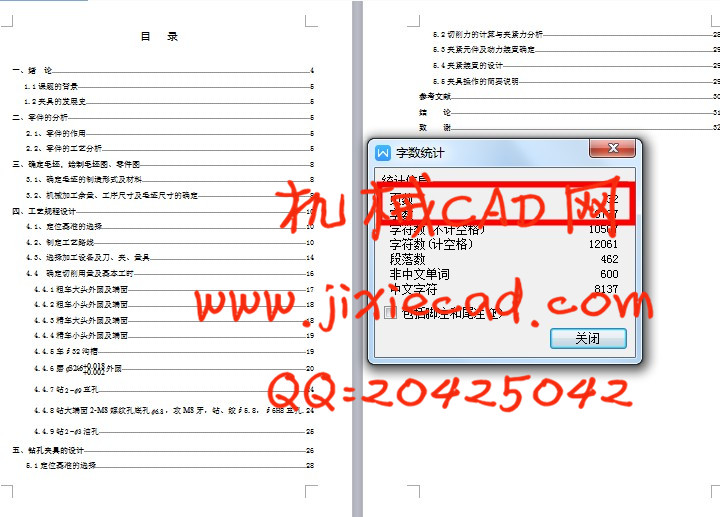
目 录
【关键词】pneumatic manipulator 、cylinder、pneumatic loop
目 录
一、绪 论 4
1.1课题的背景 5
1.2夹具的发展史 5
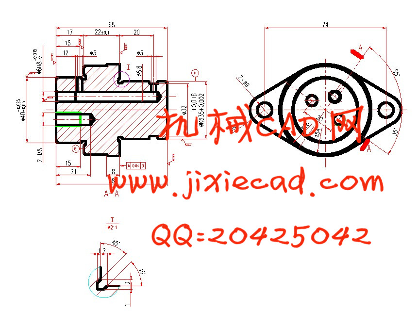
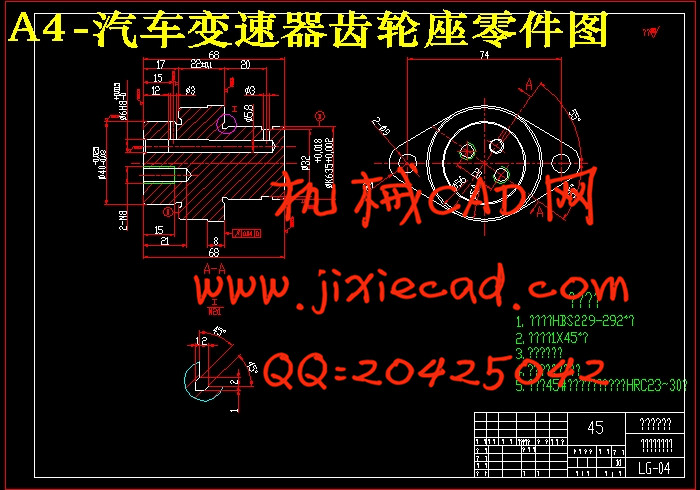
二、零件的分析 5
2.1、零件的作用 5
2.2、零件的工艺分析 5
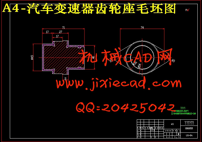
三、确定毛坯,绘制毛坯图、零件图 8
3.1、确定毛坯的制造形式及材料 8
3.2、机械加工余量、工序尺寸及毛坯尺寸的确定 8
四、工艺规程设计 10
4.1、定位基准的选择 10
4.2、制定工艺路线 10
4.3、选择加工设备及刀、夹、量具 14
4.4 确定切削用量及基本工时 16
4.4.1粗车大头外圆及端面 17
4.4.2粗车小头外圆及端面 18
4.4.3精车大头外圆及端面 18
4.4.4精车小头外圆及端面 19
4.4.5车∮32沟槽 19
4.4.6磨
4.4.7钻
4.4.8钻大端面2-M8螺纹孔底孔
4.4.9钻
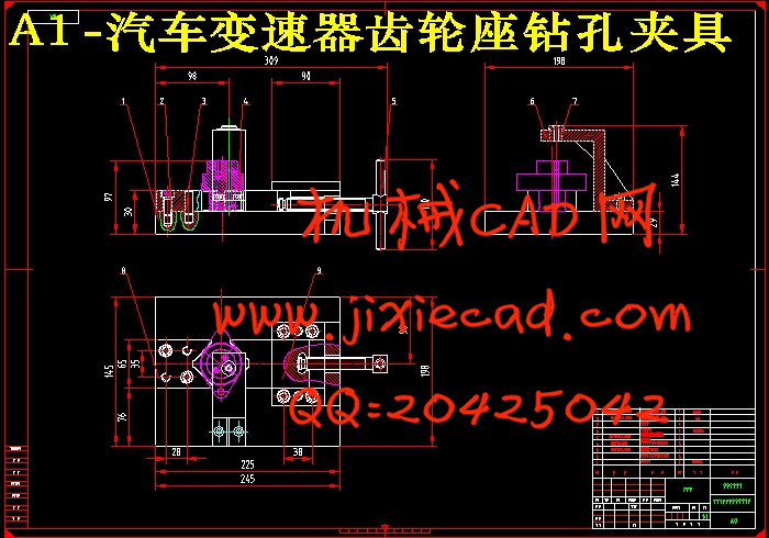
五、钻孔夹具的设计 26
5.1定位基准的选择 28
5.2切削力的计算与夹紧力分析 28
5.3夹紧元件及动力装置确定 29
5.4夹紧装置的设计 29
5.5夹具操作的简要说明 29
参考文献 30
结 论 31
致 谢 32