设计简介
摘要
本设计介绍了汽车变速箱镗孔组合机床的设计,其中包含了零件加工工艺的确定,设计中首先要了解工件的加工工艺路线及工序的计算,确定镗孔主轴的直径,初步选用电机型号及机床各部分部件。编制三图一卡(被加工零件工序图,加工示意图,机床联系尺寸图,机床生产率计算卡)。在多轴箱设计中,确定传动系统,计算主轴坐标,传动部件的校核及主轴箱的总图绘制。
本设计将车床和卧式镗床结构有机地结合为一体,降低了机器成本,而且节省了加工时间,提高了工作生产效率。
关键词:变速箱 主轴 总图绘制 多轴箱
Abstract
The design on the Box axlebox more than the design, which includes parts of the processing technology of identification, design is first necessary to understand the workpiece in the processing line and process of calculation to determine Tapping the spindle diameter, the initial choice of motor Model and some parts of the machine. Figure 1 of the three cards (the processing parts process map, diagram processing, machine tools Contact size map, machine tool productivity calculation card). In multi-axle box design, drive system established to calculate coordinates spindle, transmission parts of the spindle box and check the total mapping.
This design will be drilling, tapping combination of the two as one and reduce the cost of machinery, processing and save time, improve the work efficiency of production.
Key words: Box The Combination of Machine Tools Design multi-axle Box Tapping
目录
摘要 I
Abstract II
第一章 绪论 4
1.1 本课题研究的背景及意义 4
1.2 本课题国内外研究概况 6
1.3 本论文主要工作及结构 9
第二章 组合机床总体设计 13
2.1 组合机床工艺方案拟定 16
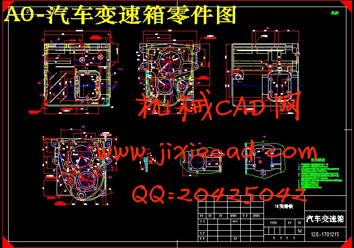
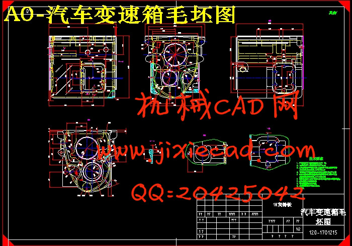
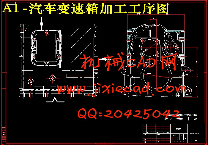
2.2 加工工序图 17
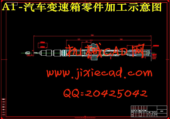
2.3 加工示意图 20
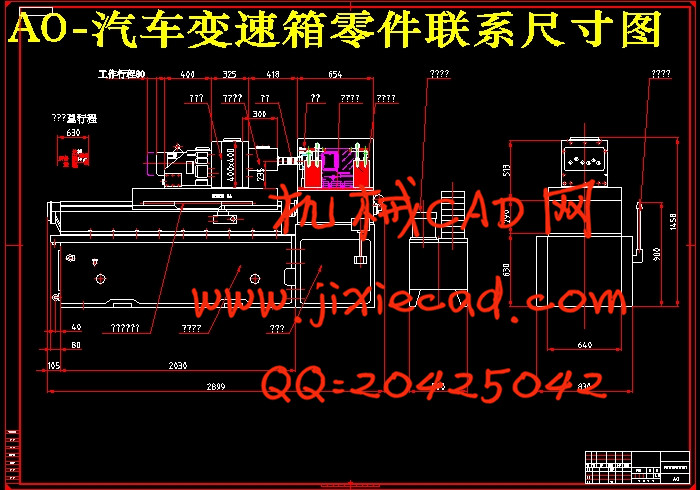
2.4 机床联系尺寸图 23
2.5 机床生产率计算卡 25
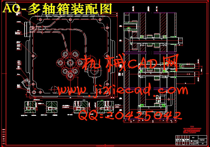
第三章 多轴箱的设计 27
3.1 多轴箱的组成及表示方法 28
3.2 多轴箱通用零件 29
3.3 绘制多轴箱原始依据图 30
3.4 主轴齿轮确定、动力计算 30
3.5 多轴箱传动系统设计 31
3.6 多轴箱坐标检查图 32
第四章 夹具设计 32
4.1 组合机床夹具概述 33
4.2 定位支撑系统 33
4.3 夹紧机构 33
4.4 夹紧力计算 33
结论 34
致谢 35
参考文献 36
本设计介绍了汽车变速箱镗孔组合机床的设计,其中包含了零件加工工艺的确定,设计中首先要了解工件的加工工艺路线及工序的计算,确定镗孔主轴的直径,初步选用电机型号及机床各部分部件。编制三图一卡(被加工零件工序图,加工示意图,机床联系尺寸图,机床生产率计算卡)。在多轴箱设计中,确定传动系统,计算主轴坐标,传动部件的校核及主轴箱的总图绘制。
本设计将车床和卧式镗床结构有机地结合为一体,降低了机器成本,而且节省了加工时间,提高了工作生产效率。
关键词:变速箱 主轴 总图绘制 多轴箱
Abstract
The design on the Box axlebox more than the design, which includes parts of the processing technology of identification, design is first necessary to understand the workpiece in the processing line and process of calculation to determine Tapping the spindle diameter, the initial choice of motor Model and some parts of the machine. Figure 1 of the three cards (the processing parts process map, diagram processing, machine tools Contact size map, machine tool productivity calculation card). In multi-axle box design, drive system established to calculate coordinates spindle, transmission parts of the spindle box and check the total mapping.
This design will be drilling, tapping combination of the two as one and reduce the cost of machinery, processing and save time, improve the work efficiency of production.
Key words: Box The Combination of Machine Tools Design multi-axle Box Tapping
目录
摘要 I
Abstract II
第一章 绪论 4
1.1 本课题研究的背景及意义 4
1.2 本课题国内外研究概况 6
1.3 本论文主要工作及结构 9
第二章 组合机床总体设计 13
2.1 组合机床工艺方案拟定 16
2.2 加工工序图 17
2.3 加工示意图 20
2.4 机床联系尺寸图 23
2.5 机床生产率计算卡 25
第三章 多轴箱的设计 27
3.1 多轴箱的组成及表示方法 28
3.2 多轴箱通用零件 29
3.3 绘制多轴箱原始依据图 30
3.4 主轴齿轮确定、动力计算 30
3.5 多轴箱传动系统设计 31
3.6 多轴箱坐标检查图 32
第四章 夹具设计 32
4.1 组合机床夹具概述 33
4.2 定位支撑系统 33
4.3 夹紧机构 33
4.4 夹紧力计算 33
结论 34
致谢 35
参考文献 36