设计简介
摘 要
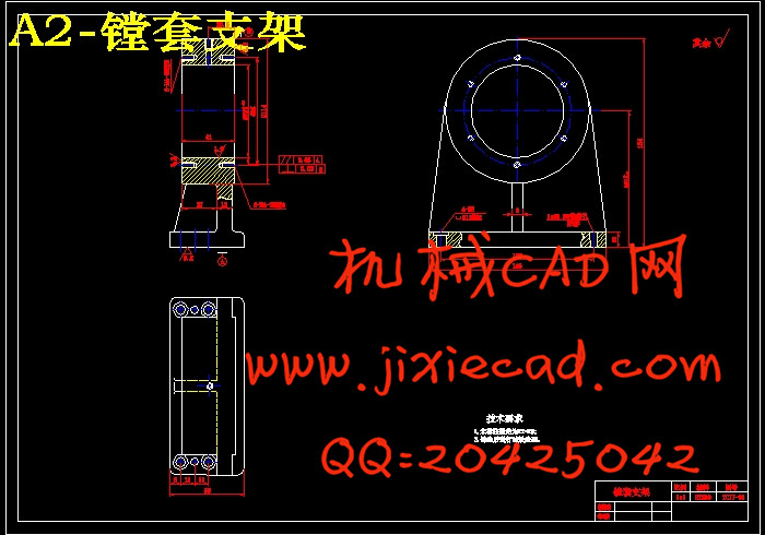
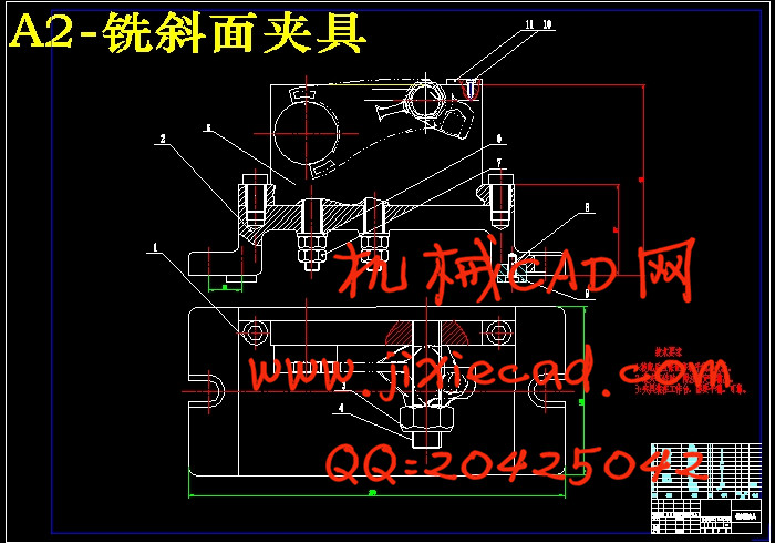
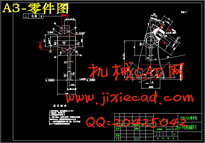
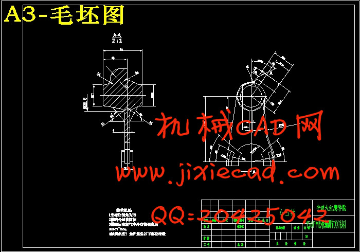
本文是对156FM凸轮轴调节叉零件加工应用及加工的工艺性分析,主要包括对零件图的分析、毛坯的选择、零件的装夹、工艺路线的制订、刀具的选择、切削用量的确定、加工工艺文件的填写。选择正确的加工方法,设计合理的加工工艺过程。此外还对156FM凸轮轴调节叉零件的两道工序的加工设计了专用夹具.机床夹具的种类很多,其中,使用范围最广的通用夹具,规格尺寸多已标准化,并且有专业的工厂进行生产。而广泛用于批量生产,专为某工件加工工序服务的专用夹具,则需要各制造厂根据工件加工工艺自行设计制造。本论文夹具设计的主要内容是设计镗床夹具和铣床夹具,最后设计了一副检验夹具。
关键词:调节叉,加工工艺,加工方法,工艺文件,夹具
Abstract
This article is on the156FM camshaft adjusting fork parts processing application and processing technology and analysis, including the spare parts diagram analysis, the choice of blank, parts of the clamping, the craft route making, tool selection, the determination of cutting conditions, processing documents. Choose the correct processing method, the rational design of machining process. In addition to the156FM camshaft adjusting fork parts of the two process designing special fixture.Machine tool fixture of many kinds, among them, the most widely used common fixture, size specifications have been standardized, and a professional production plant. While widely used in batch production, designed for a certain workpiece processing services for the fixture, it needs each factory according to workpiece machining technology to design and manufacture. In this paper, fixture design are the main contents of design jig boring machine and milling fixture, the design of a test fixture.
Key Words:Adjust the fork,Processing technology, processing method, process documentation, fixture
目 录
摘 要 IAbstract 1
目 录 2
第1章 绪论 1
1.1 机械加工工艺概述 1
1.2机械加工工艺流程 1
1.3夹具概述 2
1.4机床夹具的功能 2
1.5机床夹具的发展趋势 3
1.5.1机床夹具的现状 3
1.5.2现代机床夹具的发展方向 4
第2章156FM凸轮轴调节叉的加工工艺规程设计 5
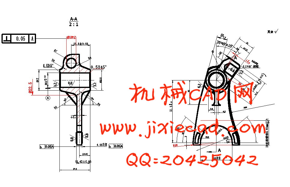
2.1零件的分析 5
2.1.1零件的作用 5
2.1.2零件的工艺分析 5
2.2确定生产类型 6
2.3确定毛坯 6
2.3.1确定毛坯种类 6
2.3.2确定锻件加工余量及形状 6
2.3.3绘制锻件零件图 6
2.4工艺规程设计 7
2.4.1选择定位基准 7
2.4.2制定工艺路线 7
2.4.3选择加工设备和工艺设备 9
2.4.4机械加工余量、工序尺寸及公差的确定 10
2.5确定切削用量及基本工时 11
2.5.1工序1:粗精铣Φ12H7的两侧面 11
2.5.3工序3:钻Φ12H7的通孔 13
2.5.4工序5:铰Φ12H7的通孔 15
2.5.5工序6:粗铣Φ12H7的两侧面 16
2.5.6工序7:粗铣Φ26孔的两面 17
2.5.7工序8:精铣Φ26孔的两面 18
2.5.8工序10:铣斜面 19
2.5.9工序13:钻铰Φ8的孔 20
2.6本章小结 22
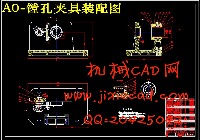
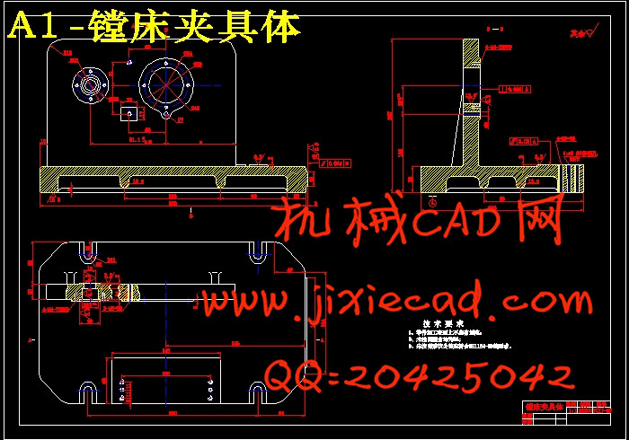
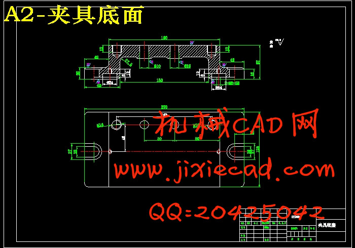
第3章 镗孔夹具设计 23
3.1问题的提出 23
3.2 定位、夹紧方案的选择 23
3.3切削力及夹紧力的计算 24
3.4 误差分析与计算 25
3.5 零、部件的设计与选用 26
3.6 夹具设计及操作的简要说明 27
3.7 本章小结 27
第4章 铣床夹具设计 29
4.1问题的指出 29
4.2定位基准的选择 29
4.3 定位方案和元件设计 29
4.4 夹紧机构的设计 29
4.5定位误差的计算 29
4.6 本章小结 30
第5章 检验夹具的设计 31
5.1题的指出 31
5.2定位基准的选择 31
5.3检验夹具设计 31
5.4检验夹具检测项目 32
5.5 本章小结 32
结 论 33
参 考 文 献 34