设计简介
异型杠杆零件车削夹具设计与零件加工
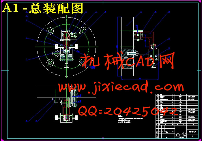
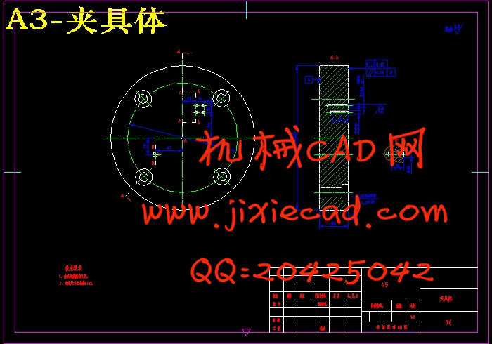
摘 要 机械加工工艺是实现产品设计,保证产品质量,节约能源,降低消耗的重要手段。异形杠杆是可用于连接其他零件起到杠杆支撑原理的零件,对异形杠杆的基本要求是高强度、高韧性、高耐磨性和回转平稳性。本课题以该异型杠杆为研究对象,通过对异型杠杆零件图的分析,明确了零件的结构特点及技术要求,拟订了较为合理的机械加工工艺规程,编制了详细的机械加工工艺卡。在确定零件装夹定位方案的基础上,完成了异型杠杆车削夹具设计,该夹具简单可靠,保证了被加工零件的形状位置精度,提高了生产率。最后根据设计标准,制作了夹具实物模型。
关键词 异型杠杆 加工工艺 夹具设计 零件
Abstract Machining process is to achieve product design, to ensure product quality, save energy, reduce consumption of the important means. Shaped lever can be used to connect other parts of the principle of leverage support parts, a basic requirement is a high strength, high toughness, high wear resistance and rotary stability of the shaped lever.The topics to Shaped lever part turning fixture design and parts processing as the research object, firstly, through the analysis of the part drawing, understand the parts of the structure, clear the specific requirements, again developed a more reasonable machining process and prepared a detailed machining process card. Completed on the basis of the positioning program identified by Part clamping the shaped lever turning fixture design, the jig is simple and reliable, and to ensure that the shape of the part to be machined positional accuracy and improve productivity. Finally, according to the design standards, I made the fixture mock-ups.
Keywords Shaped lever Machining process Fixture design Parts processing
目 录
摘 要 I
第一章 绪论 1
1.1 夹具概述 1
1.1.1 夹具概念 1
1.1.2 夹具的主要功能 1
1.1.3 夹具的分类 1
1.2 夹具的组成 1
1.3 夹具研究的目的和意义 2
1.4 夹具设计研究现状、发展方向与要求 2
第二章 零件分析 4
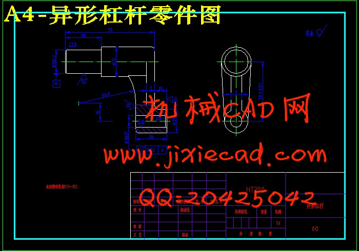
2.1 零件图工艺性分析 4
2.1.1 零件结构功用分析 4
2.1.2 零件技术条件分析 4
2.1.3 零件结构工艺性分析 4
2.1.4 零件图 4
2.2 毛坯选择 5
第三章 机械加工工艺规程制订 7
3.1 机加工工艺路线确定 7
3.1.1 加工方法分析与确定 7
3.1.2 加工顺序的安排 7
3.2 设备及其工艺装备确定 7
3.3 切削用量及工时定额确定 7
第四章 夹具设计 11
4.1 概述 11
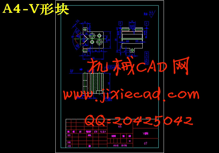
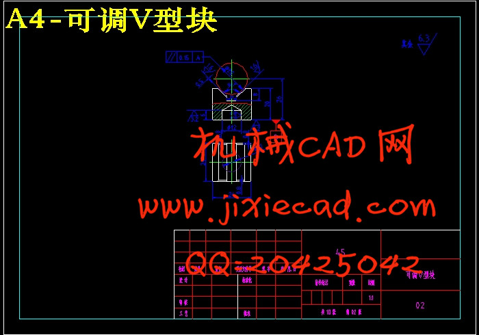
4.2 定位方案确定 11
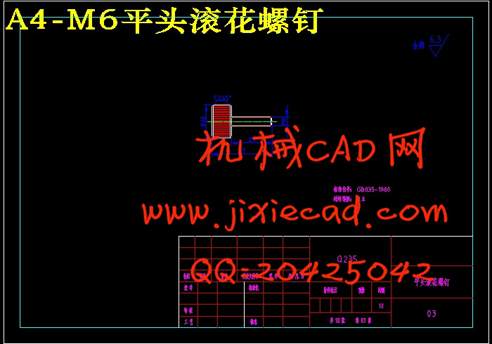
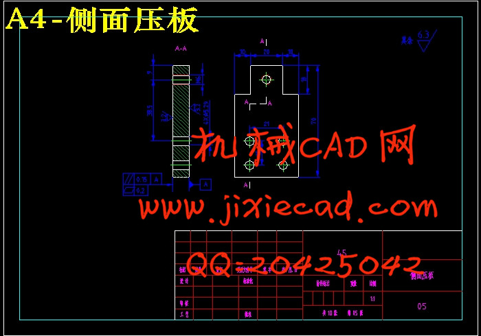
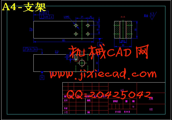
4.3 夹具设计及操作的简要说明 11
4.4 切削力及夹紧力的分析计算 14
4.5 定位误差的分析与计算 14
第五章 刀具和量具的设计 16
5.1 刀具的设计 16
5.2 量具的设计 17
5.2.1 量具类型确定 17
5.2.2 极限量具尺寸公差确定 17
结 论 18
致 谢 语 19
参 考 文 献 20
摘 要 机械加工工艺是实现产品设计,保证产品质量,节约能源,降低消耗的重要手段。异形杠杆是可用于连接其他零件起到杠杆支撑原理的零件,对异形杠杆的基本要求是高强度、高韧性、高耐磨性和回转平稳性。本课题以该异型杠杆为研究对象,通过对异型杠杆零件图的分析,明确了零件的结构特点及技术要求,拟订了较为合理的机械加工工艺规程,编制了详细的机械加工工艺卡。在确定零件装夹定位方案的基础上,完成了异型杠杆车削夹具设计,该夹具简单可靠,保证了被加工零件的形状位置精度,提高了生产率。最后根据设计标准,制作了夹具实物模型。
关键词 异型杠杆 加工工艺 夹具设计 零件
Abstract Machining process is to achieve product design, to ensure product quality, save energy, reduce consumption of the important means. Shaped lever can be used to connect other parts of the principle of leverage support parts, a basic requirement is a high strength, high toughness, high wear resistance and rotary stability of the shaped lever.The topics to Shaped lever part turning fixture design and parts processing as the research object, firstly, through the analysis of the part drawing, understand the parts of the structure, clear the specific requirements, again developed a more reasonable machining process and prepared a detailed machining process card. Completed on the basis of the positioning program identified by Part clamping the shaped lever turning fixture design, the jig is simple and reliable, and to ensure that the shape of the part to be machined positional accuracy and improve productivity. Finally, according to the design standards, I made the fixture mock-ups.
Keywords Shaped lever Machining process Fixture design Parts processing
目 录
摘 要 I
第一章 绪论 1
1.1 夹具概述 1
1.1.1 夹具概念 1
1.1.2 夹具的主要功能 1
1.1.3 夹具的分类 1
1.2 夹具的组成 1
1.3 夹具研究的目的和意义 2
1.4 夹具设计研究现状、发展方向与要求 2
第二章 零件分析 4
2.1 零件图工艺性分析 4
2.1.1 零件结构功用分析 4
2.1.2 零件技术条件分析 4
2.1.3 零件结构工艺性分析 4
2.1.4 零件图 4
2.2 毛坯选择 5
第三章 机械加工工艺规程制订 7
3.1 机加工工艺路线确定 7
3.1.1 加工方法分析与确定 7
3.1.2 加工顺序的安排 7
3.2 设备及其工艺装备确定 7
3.3 切削用量及工时定额确定 7
第四章 夹具设计 11
4.1 概述 11
4.2 定位方案确定 11
4.3 夹具设计及操作的简要说明 11
4.4 切削力及夹紧力的分析计算 14
4.5 定位误差的分析与计算 14
第五章 刀具和量具的设计 16
5.1 刀具的设计 16
5.2 量具的设计 17
5.2.1 量具类型确定 17
5.2.2 极限量具尺寸公差确定 17
结 论 18
致 谢 语 19
参 考 文 献 20