设计简介
摘 要
随着自动化生产能力的提高,现代工厂中出现需要组合机床的场合越来越多,组合机床是以通用部件为基础,配以工件特定外形和加工工艺设计的专用部件和夹具,组成的半自动或自动专用机床。它一般采用多轴,多刀,多工序,多面或多工位同时加工的方式,生产效率比通用机床高几倍至几十倍。由于通用部件已经标准化合系列化,可根据需要灵活配置,能缩短设计和制造周期。因此,组合机床兼有低成本和高效率的优点,在大批量生产中得到广泛应用,并可用以组成自动生产线。本设计中,在充分数据计算的基础上对标准通用零件做了仔细选择,并依据被加工零件的结构特点,加工部位的尺寸精度,表面粗糙度要求,以及定位夹紧方式,工艺方法和加工过程中所采用的刀具,生产率,切削用量情况等设计了结构合理的多轴箱。
关键词: 组合机床,多轴箱,工艺流程,钻削
Abstract
With automatic production capability is improved, the modern factories in need of modular machine tool, the combination of more occasions based on general parts, match with workpiece specific shape and process design of special components and fixtures, composed of semi-automatic or automatic special machine. It usually adopts the multiaxial, knife, processes, and multi-faceted or multistage and processing, production efficiency than general machine high several times or more. Due to the common parts have standard series, can according to the combined flexible configuration, can shorten the cycle of design and manufacture. Therefore, the combination machine has the advantages of low cost and high efficiency, in large, mass production is widely used, and the automatic production line can be used to composition.In this design, all the standard parts selection based on the carefully data calculation, and according to the characteristics of the structure by processing components, precision machining parts size, surface roughness, and the localization way, clamping technology and processing process using tools, cutting dosages as productivity, the structure design of reasonable spindle box.
Keywords:combined machine tool, production efficiency, clamp,drilling
目 录
摘 要 2
Abstract 3
引 言 6
1 工艺方案的拟定 8
1.1被加加工工序工零件的加工精度 8
1.2被加工零件的特点 8
1.3零件的生产批量 8
1.4机床使用条件 8
2 定位基准及夹位点选择 9
3 组合机床总体设计——三图一卡 11
3.1被加工零件工序图 11
3.1.1被加工零件工序图的设计 11
3.1.2主轴箱的分布 11
3.2加工示意图 12
3.3动力部件的选择 14
3.4组合机床生产率的计算 16
3.4.1机床实际生产率的计算 16
3.4.2理想生产率Q 18
3.4.3机床负荷率 18
3.4.4生产率计算卡 18
3.5机床联系尺寸图 19
3.5.1联系尺寸图的作用 19
3.5.2机床装料高度的确定 19
3.5.3夹具轮廓尺寸的确定 20
3.5.4中间底座尺寸的确定 21
3.5.5动力部件总选种的确定 22
4.夹具设计 23
4.1设计步骤 23
4.2 定位支承系统 23
4.3定位误差的分析计算 24
5.导向装置 27
6.夹紧力的确定 28
7.夹紧机构 30
7.1设计夹紧机构时,应注意满足以下的基本要求: 30
7.2.夹紧气缸 31
7.3.活塞杆的计算 32
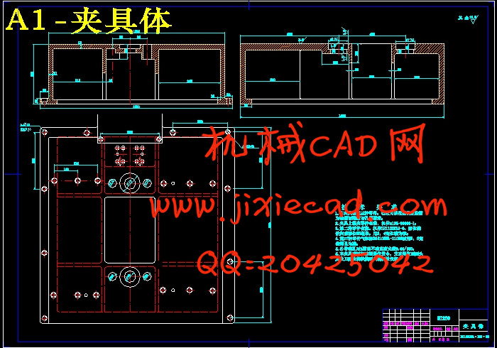
8.夹具体设计 33
8.1对夹具体的要求: 33
8.2夹具体的技术要求 33
结 束 语 35
致 谢 36
参考文献 37