设计简介
摘 要
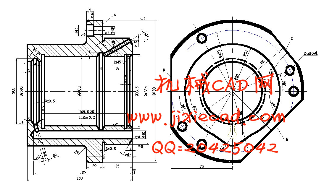
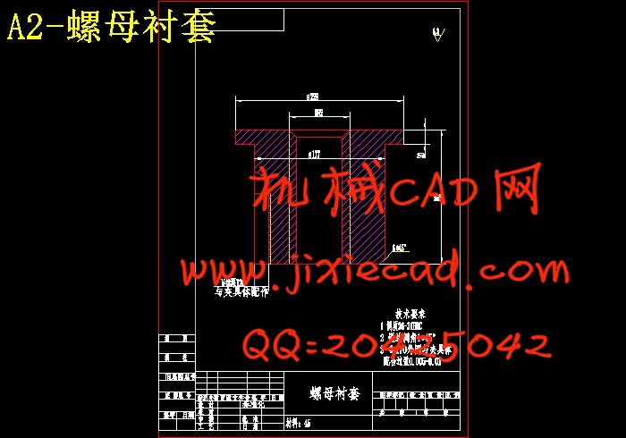
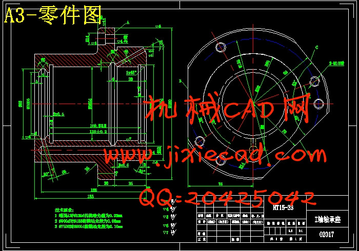
本设计是CA6140床头I轴轴承座零件的加工工艺规程及一些工序的专用夹具设计。CA6140I轴轴承座零件的主要加工表面是平面及孔。一般来说,保证平面的加工精度要比保证孔的加工精度容易。因此,本设计遵循先面后孔的原则。并将孔与平面的加工明确划分成粗加工和精加工阶段以保证孔的加工精度。基准的选择以I轴轴承座外圆面作为粗基准。先将底面加工出来,然后作为定位基准,在以底面作为精基准加工孔。整个加工过程选用数控机床。在夹具方面选用专用夹具。考虑到零件的结构尺寸简单,夹紧方式多采用手动夹紧,夹紧简单,机构设计简单,且能满足设计要求。关键词 加工工艺,夹具,定位,夹紧
ABSTRACT
This paper is to design the craft processes of making the CA6140 lever spare parts and some specialized tongs in the process. The CA6140 lever spare part primarily processes the surface and bores. Generally speaking, to guarantee the accuracy of the flat surface process is easier than that of the bore. Therefore, this design follows the principle that surface first and then the bore, and definitely divides the process of flat surface and bore into coarse processes and precise processes to guarantee the bore processes. The basic choice is to consider 45 outside circle as rough basis and to consider 25 bore and its next surface as precise basis. The bottom is first processed out to be fixed position basis, and process the bore using the bottom as the precise basis. The whole processes choose the machine bed. In the aspects of tongs choosing, specialized tongs are used. In consideration of the simple construction size of the spare parts, clipping by hands is adopted. It is simple, and the organization design is simple, and can satisfy the design request.
Key Words craft proces , tongs, fixed position, tight clip
目 录
摘 要 Ⅰ
Abstract Ⅱ
1 绪论 3
1.1课题背景 3
1.2夹具的发展史 3
1.3小结 4
2 I轴轴承座加工工艺规程设计 5
2.1零件的分析 5
2.1.1零件的作用 5
2.1.2零件的工艺分析 5
2.2确定生产类型 5
2.3确定毛坯 5
2.3.1确定毛坯种类 5
2.3.2确定铸件加工余量及形状 5
2.3.3绘制铸件零件图 5
2.4工艺规程设计 6
2.4.1选择定位基准 6
2.4.2制定工艺路线 8
2.4.3选择加工设备和工艺设备 8
2.4.4机械加工余量、工序尺寸及公差的确定 9
2.5确定切削用量及基本工时 11
2.5.1工序1:车肩胛面成型 11
2.5.2工序2:钻,扩φ75中孔,车端面,倒角 12
2.5.3工序3:挖环槽 14
2.5.4工序4:钻Φ14及3-Φ9的通孔 15
2.5.5工序5:攻M10×1.5的螺纹 16
2.5.6工序6:铣B,D,C三平面 17
2.5.7工序7:钻Φ10的孔 17
2.5.8工序8:钻Φ5短斜孔 19
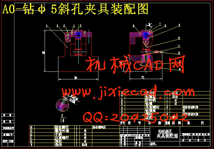
2.5.9工序9:钻Φ5长斜孔 20
2.5.10工序10:粗镗Φ90的孔 21
2.5.11工序11:精镗孔Φ90 22
2.6本章小结 23
3 专用夹具设计 24
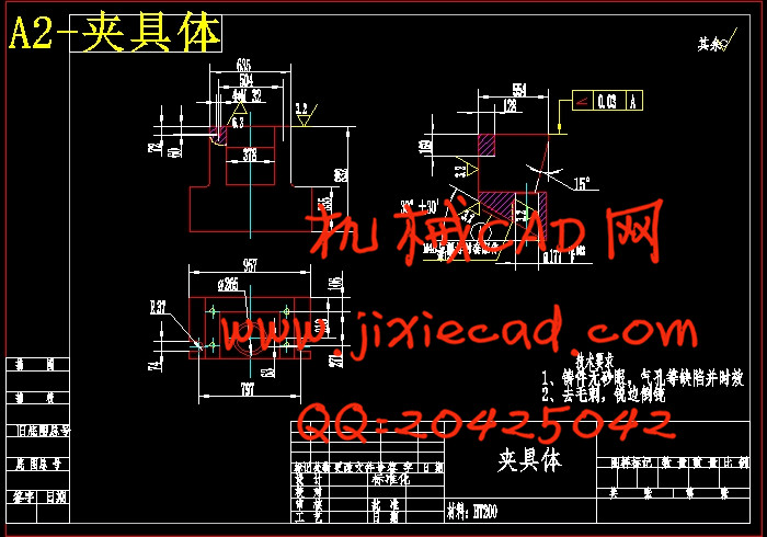
3.1钻φ5长斜孔夹具设计说明书 24
3.1问题的提出 24
3.2夹具的设计 29
3.3本章小结 29
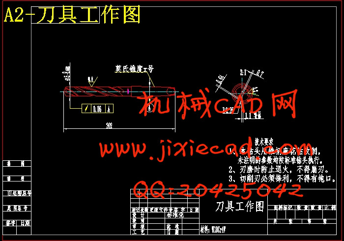
4 钻φ5长斜孔刀具设计说明书 30
4.1刀具类型的确定 30
4.2刀具设计参数的确定 30
4.3刀具工作草图的确定 30
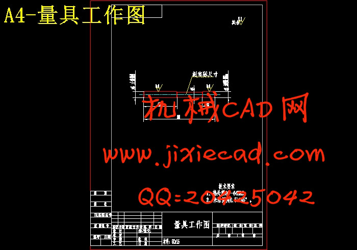
5 钻φ5长斜孔量具设计说明书 31
5.1量具类型的确定 31
5.2极限量具尺寸公差的确定 31
5.3极限量具尺寸公差图的确定 31
5.4极限量具结构设计 31
5.5本章小结 31
6 第一道工序数控编程说明书 33
7 设计体会 34
参考文献 36
致 谢 37