设计简介
摘要
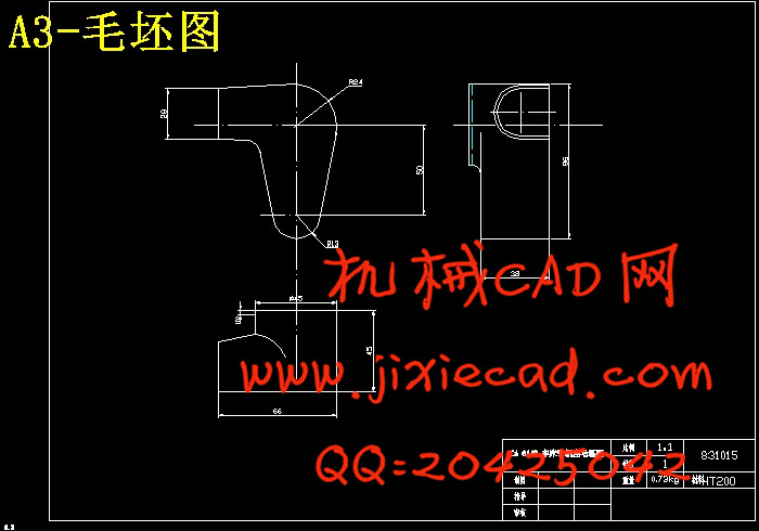
本次设计是设计CA6140车床手柄座,内容包括零件的分析,工艺路线的制定,工艺规划设计,某道工序的夹具设计以及该道工序的工序卡,机械加工综合卡片,夹具装配图以及夹具底座零件图的绘制等等。
我们首先对手柄座的结构特征、用途以及其工艺规程进行了详细的分析,然后确定了一套合理加工方案,加工方案要求简单,并能保证加工质量。由于手柄座各表面的精度要求比较高,所以我们在加工一些主要平面时都要先粗铣然后半精铣,加工一些孔时要进行钻、粗铰然后还要进行精铰工序。因为手柄座的加工质量将直接影响其性能和使用寿命,所以每一道工序都必须要达到其加工要求。
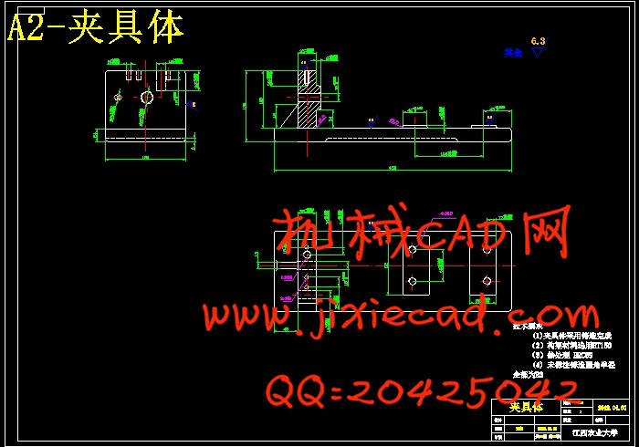
此外,本设计的生产类型是大量生产的加工方案,为了提高劳动生产率,降低劳动强度,保证加工质量,需设计专用夹具,本设计是设计加工CA6140车床手柄座φ14H7mm孔工序的夹具。
关键词:CA6140车床手柄座;工艺规程;专用夹具设计;夹具装配图
Abstract
This design is about CA6140 lathe handle seat, and the content includes the components analysis, the formulation of process route, and the process planning design, fixture design to a process and process card to the process, the assembly drawing and fixture base component drawing, and so on.
We first analyze the structure, the use and the technical process of the handle in detail, and then we determine a reasonable processing scheme. And the processing plan requires that it should be simple, and it also can guarantee the processing quality. Because the surface precision demand of a handle is higher, so we should do rough milling first and then half-fine milling in processing of some major plane, when we processing some holes, we should drilling and reaming first, and then fine-hinge in the process. Because the processing quality of a handle will directly influence the performance and the long service life, so every procedure must be achieved its processing requirements.
Otherwise, as we know the production type of this design is mass production, in order to improve the productivity of labor, to reduce the labor intensity, to guarantee the machining quality, we need to design special fixture, and in this design, we should design a fixture which it can help us processing a φ14H7mm hole in CA6140 lathe handle.
Key words: CA6140 lathe handle seat; Process planning; Special fixture design; Fixture assembly drawing
目录
中文摘要…………………………………………………………………………… I
英文摘要…………………………………………………………………………… II
(一)机械加工工艺规程设计…………………………………………………… 1
第一章 手柄座用途及工艺分析………………………………………………… 1
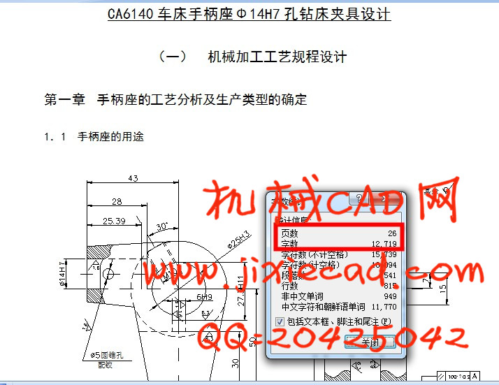
1.1 手柄座的用途……………………………………………………………… 1
1.2 手柄座的技术要求………………………………………………………… 2
1.3 审查手柄座的工艺性……………………………………………………… 2
1.3.1 孔的加工……………………………………………………………… 3
1.3.2 面的加工……………………………………………………………… 3
1.3.3 槽的加工……………………………………………………………… 3
1.3.4 螺纹孔的加工………………………………………………………… 3
第二章 确定生产类型和毛坯的制造型………………………………………… 3
2.1 确定生产类型……………………………………………………………… 3
2.2 毛坯的制造形式…………………………………………………………… 4
第三章 拟定手柄座工艺路线…………………………………………………… 4
3.1 定位基准的选择…………………………………………………………… 4
3.1.1 精基的选择…………………………………………………………… 4
3.1.2 粗基准的选择………………………………………………………… 4
3.2 表面加工方法的确定……………………………………………………… 5
3.3 加工阶段的划分…………………………………………………………… 5
3.3.1 粗加工阶段…………………………………………………………… 5
3.3.2 半精加工阶段………………………………………………………… 6
3.3.3 精加工阶段…………………………………………………………… 6
3.4 工艺路线方案的拟定与比较……………………………………………… 6
3.4.1 工艺路线方案一……………………………………………………… 6
3.4.2 工艺路线方案二……………………………………………………… 7
3.4.3 工艺路线方案的比较与分析………………………………………… 7
第四章 机械加工余量,工序尺寸和毛坯尺寸的确定………………………… 8
4.1 查表确定加工余量………………………………………………………… 8
4.2 φ45圆柱两端面毛坯尺寸及加工余量确定……………………………… 9
4.3 φ14H7孔端面毛坯尺寸及加工余量计算………………………………… 9
4.4 钻-粗铰-精铰φ14mm孔的加工余量,工序尺寸和公差的确定……… 10
4.5 其他尺寸及其加工余量的确定…………………………………………… 10
第五章 切屑用量,时间定额的计算………………………………………………11
5.1 确定各工序切屑用量及基本工时………………………………………… 11
5.1.1 工序I:粗铣φ45mm圆柱大端面…………………………………… 11
5.1.2 工序II:粗铣,半精铣φ45mm圆柱小端面…………………………12
5.1.3 工序III:钻-粗铰-精铰φ25H8孔………………………………… 12
5.1.4 工序IV:钻。铰φ10H7mm孔…………………………………………13
5.1.5 工序V:铣键槽…………………………………………………………13
5.1.6 工序VI:钻-粗铰-精铰φ14H7mm孔……………………………… 14
5.1.7 工序VII:钻,攻M10螺纹孔……………………………………… 14
5.1.8 工序VIII:钻-粗铰-精铰φ5.5mm孔…………………………… 15
(二) 专用夹具的设计…………………………………………………………… 16
第六章 夹具体的设计…………………………………………………………… 16
6.1 定位方案设计……………………………………………………………… 16
6.1.1 工件的定位基准及定位基面………………………………………… 16
6.1.2 定位方案的选取与比较……………………………………………… 17
6.1.3 定位元件的选用与计算……………………………………………… 17
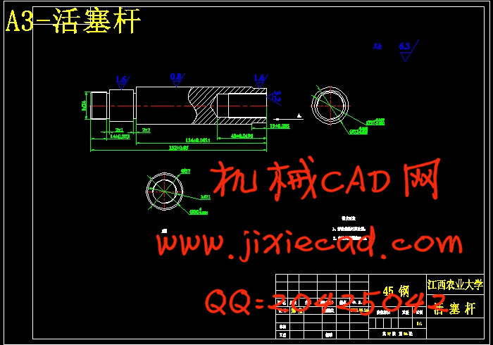
6.1.3.1 短圆柱销………………………………………………………… 17
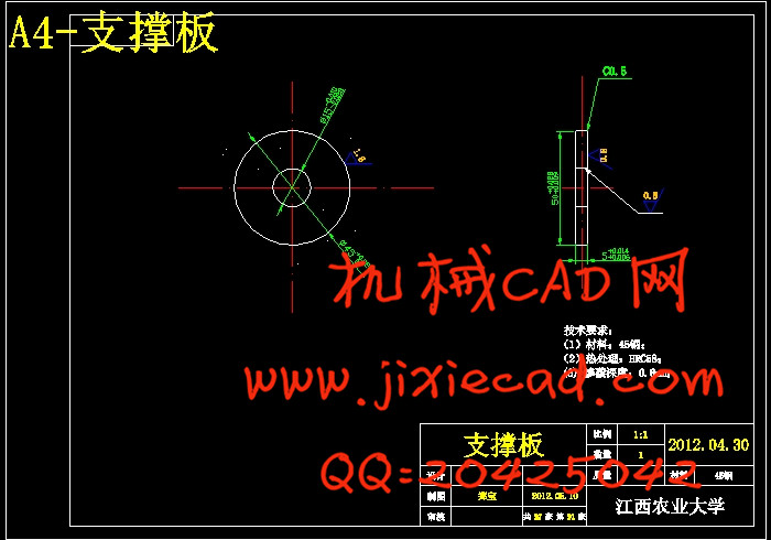
6.1.3.2 支撑板…………………………………………………………… 17
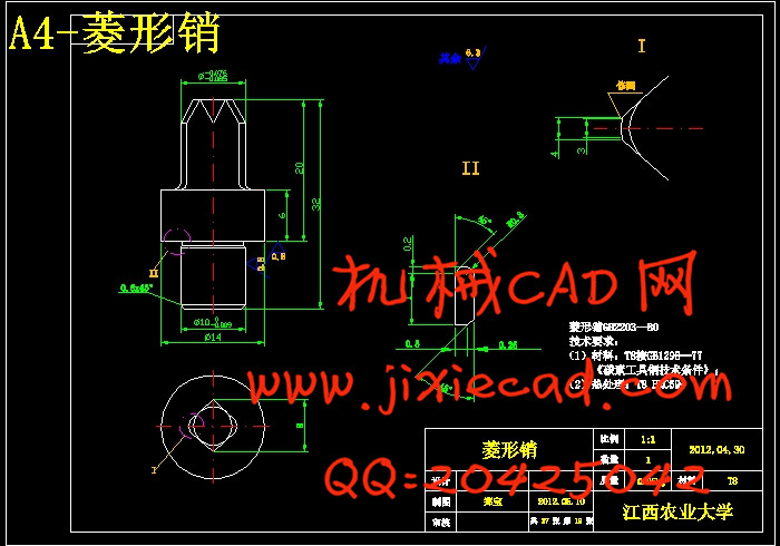
6.1.3.3 菱形销…………………………………………………………… 18
6.2 定位误差分析……………………………………………………………… 18
6.3 导向装置的设计…………………………………………………………… 18
6.3.1 钻套的设计…………………………………………………………… 19
6.3.2 钻套高度和排屑间隙………………………………………………… 19
6.3.3 钻模的设计…………………………………………………………… 19
6.4 夹紧装置设计……………………………………………………………… 20
6.4.1 夹紧装置选用原则…………………………………………………… 20
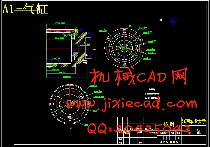
6.4.2 气压夹紧装置简介…………………………………………………… 20
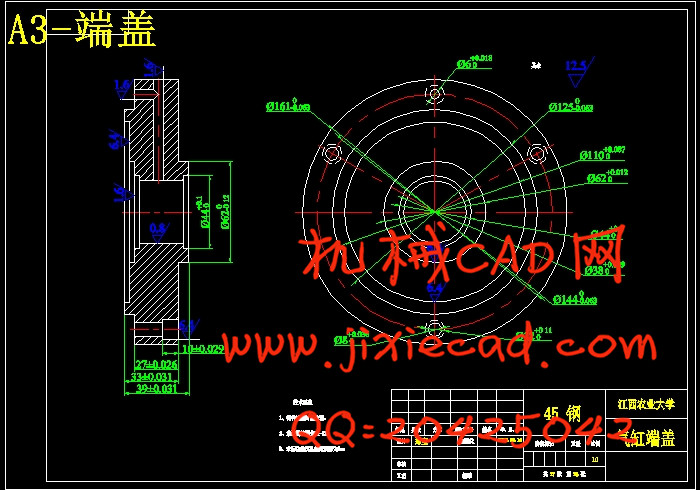
6.4.3 动力源的设计………………………………………………………… 21
6.5 夹具体构架的设计………………………………………………………… 22
第七章 夹具的操作与维护……………………………………………………… 23
总结………………………………………………………………………………… 24
参考文献…………………………………………………………………………… 25
致谢………………………………………………………………………………… 26
本次设计是设计CA6140车床手柄座,内容包括零件的分析,工艺路线的制定,工艺规划设计,某道工序的夹具设计以及该道工序的工序卡,机械加工综合卡片,夹具装配图以及夹具底座零件图的绘制等等。
我们首先对手柄座的结构特征、用途以及其工艺规程进行了详细的分析,然后确定了一套合理加工方案,加工方案要求简单,并能保证加工质量。由于手柄座各表面的精度要求比较高,所以我们在加工一些主要平面时都要先粗铣然后半精铣,加工一些孔时要进行钻、粗铰然后还要进行精铰工序。因为手柄座的加工质量将直接影响其性能和使用寿命,所以每一道工序都必须要达到其加工要求。
此外,本设计的生产类型是大量生产的加工方案,为了提高劳动生产率,降低劳动强度,保证加工质量,需设计专用夹具,本设计是设计加工CA6140车床手柄座φ14H7mm孔工序的夹具。
关键词:CA6140车床手柄座;工艺规程;专用夹具设计;夹具装配图
Abstract
This design is about CA6140 lathe handle seat, and the content includes the components analysis, the formulation of process route, and the process planning design, fixture design to a process and process card to the process, the assembly drawing and fixture base component drawing, and so on.
We first analyze the structure, the use and the technical process of the handle in detail, and then we determine a reasonable processing scheme. And the processing plan requires that it should be simple, and it also can guarantee the processing quality. Because the surface precision demand of a handle is higher, so we should do rough milling first and then half-fine milling in processing of some major plane, when we processing some holes, we should drilling and reaming first, and then fine-hinge in the process. Because the processing quality of a handle will directly influence the performance and the long service life, so every procedure must be achieved its processing requirements.
Otherwise, as we know the production type of this design is mass production, in order to improve the productivity of labor, to reduce the labor intensity, to guarantee the machining quality, we need to design special fixture, and in this design, we should design a fixture which it can help us processing a φ14H7mm hole in CA6140 lathe handle.
Key words: CA6140 lathe handle seat; Process planning; Special fixture design; Fixture assembly drawing
目录
中文摘要…………………………………………………………………………… I
英文摘要…………………………………………………………………………… II
(一)机械加工工艺规程设计…………………………………………………… 1
第一章 手柄座用途及工艺分析………………………………………………… 1
1.1 手柄座的用途……………………………………………………………… 1
1.2 手柄座的技术要求………………………………………………………… 2
1.3 审查手柄座的工艺性……………………………………………………… 2
1.3.1 孔的加工……………………………………………………………… 3
1.3.2 面的加工……………………………………………………………… 3
1.3.3 槽的加工……………………………………………………………… 3
1.3.4 螺纹孔的加工………………………………………………………… 3
第二章 确定生产类型和毛坯的制造型………………………………………… 3
2.1 确定生产类型……………………………………………………………… 3
2.2 毛坯的制造形式…………………………………………………………… 4
第三章 拟定手柄座工艺路线…………………………………………………… 4
3.1 定位基准的选择…………………………………………………………… 4
3.1.1 精基的选择…………………………………………………………… 4
3.1.2 粗基准的选择………………………………………………………… 4
3.2 表面加工方法的确定……………………………………………………… 5
3.3 加工阶段的划分…………………………………………………………… 5
3.3.1 粗加工阶段…………………………………………………………… 5
3.3.2 半精加工阶段………………………………………………………… 6
3.3.3 精加工阶段…………………………………………………………… 6
3.4 工艺路线方案的拟定与比较……………………………………………… 6
3.4.1 工艺路线方案一……………………………………………………… 6
3.4.2 工艺路线方案二……………………………………………………… 7
3.4.3 工艺路线方案的比较与分析………………………………………… 7
第四章 机械加工余量,工序尺寸和毛坯尺寸的确定………………………… 8
4.1 查表确定加工余量………………………………………………………… 8
4.2 φ45圆柱两端面毛坯尺寸及加工余量确定……………………………… 9
4.3 φ14H7孔端面毛坯尺寸及加工余量计算………………………………… 9
4.4 钻-粗铰-精铰φ14mm孔的加工余量,工序尺寸和公差的确定……… 10
4.5 其他尺寸及其加工余量的确定…………………………………………… 10
第五章 切屑用量,时间定额的计算………………………………………………11
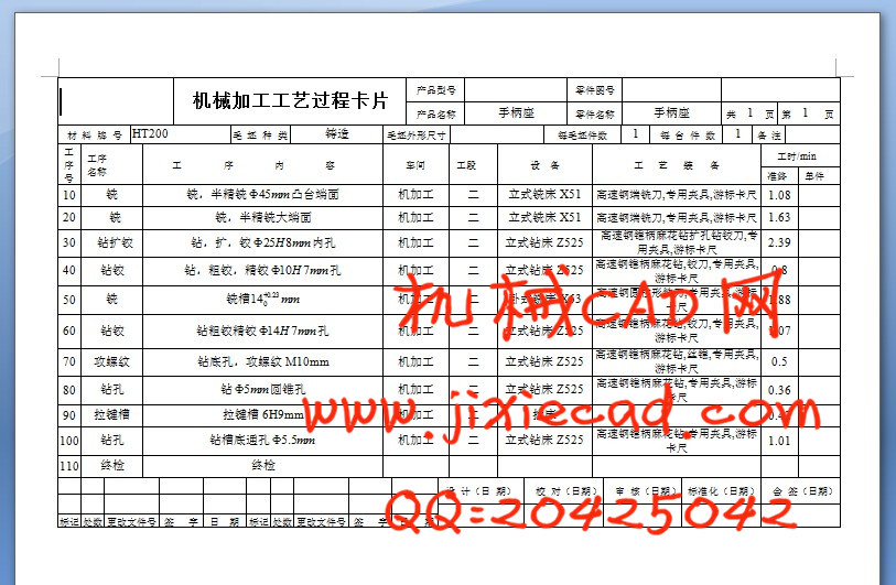
5.1 确定各工序切屑用量及基本工时………………………………………… 11
5.1.1 工序I:粗铣φ45mm圆柱大端面…………………………………… 11
5.1.2 工序II:粗铣,半精铣φ45mm圆柱小端面…………………………12
5.1.3 工序III:钻-粗铰-精铰φ25H8孔………………………………… 12
5.1.4 工序IV:钻。铰φ10H7mm孔…………………………………………13
5.1.5 工序V:铣键槽…………………………………………………………13
5.1.6 工序VI:钻-粗铰-精铰φ14H7mm孔……………………………… 14
5.1.7 工序VII:钻,攻M10螺纹孔……………………………………… 14
5.1.8 工序VIII:钻-粗铰-精铰φ5.5mm孔…………………………… 15
(二) 专用夹具的设计…………………………………………………………… 16
第六章 夹具体的设计…………………………………………………………… 16
6.1 定位方案设计……………………………………………………………… 16
6.1.1 工件的定位基准及定位基面………………………………………… 16
6.1.2 定位方案的选取与比较……………………………………………… 17
6.1.3 定位元件的选用与计算……………………………………………… 17
6.1.3.1 短圆柱销………………………………………………………… 17
6.1.3.2 支撑板…………………………………………………………… 17
6.1.3.3 菱形销…………………………………………………………… 18
6.2 定位误差分析……………………………………………………………… 18
6.3 导向装置的设计…………………………………………………………… 18
6.3.1 钻套的设计…………………………………………………………… 19
6.3.2 钻套高度和排屑间隙………………………………………………… 19
6.3.3 钻模的设计…………………………………………………………… 19
6.4 夹紧装置设计……………………………………………………………… 20
6.4.1 夹紧装置选用原则…………………………………………………… 20
6.4.2 气压夹紧装置简介…………………………………………………… 20
6.4.3 动力源的设计………………………………………………………… 21
6.5 夹具体构架的设计………………………………………………………… 22
第七章 夹具的操作与维护……………………………………………………… 23
总结………………………………………………………………………………… 24
参考文献…………………………………………………………………………… 25
致谢………………………………………………………………………………… 26