设计简介
中文摘要
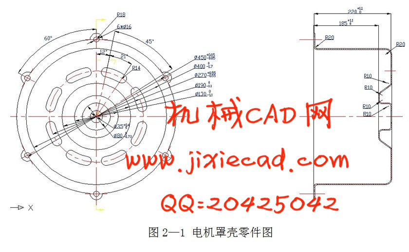
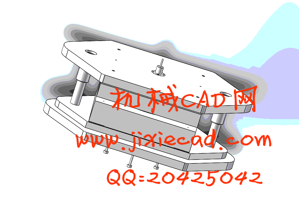
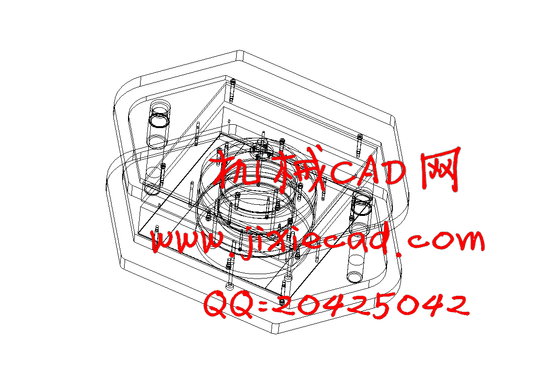
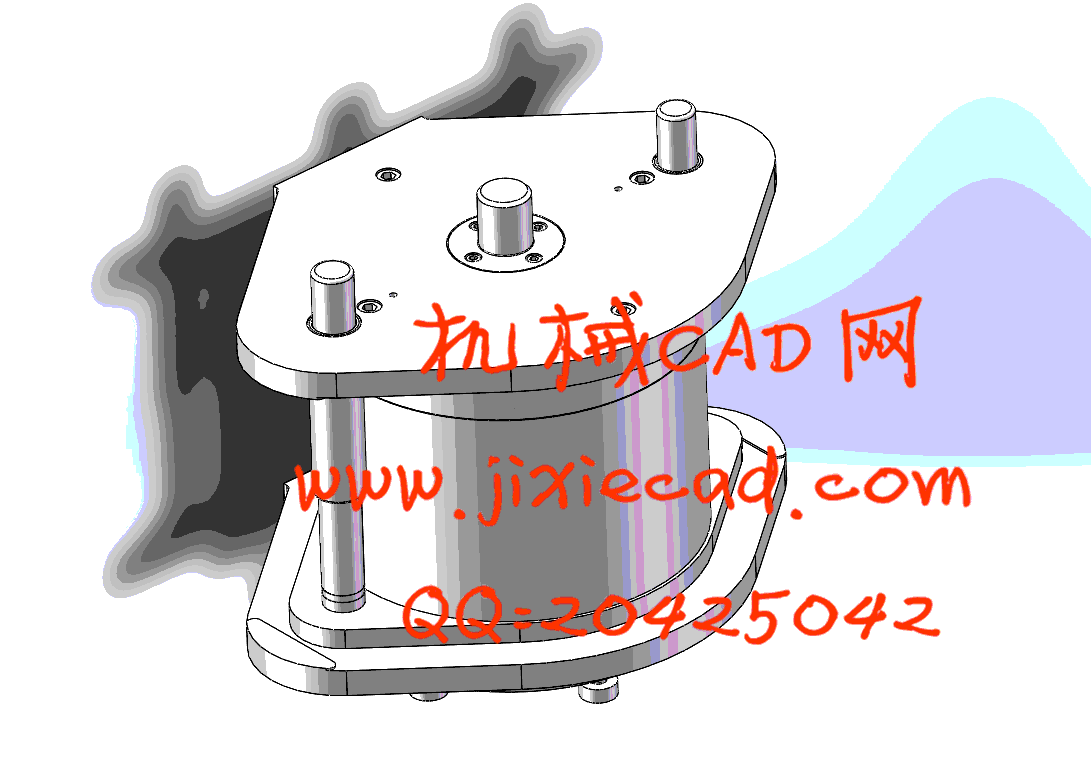
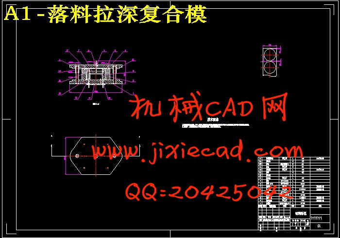
通过分析电机盖端的结构特点,确定了其冲裁工序、拉伸序及各工序件的尺寸,介绍了整体模具的工艺设计,重点分析了拉伸模结构。冲压模具的设计方法在当下已经日趋成熟,利用传统的设计手段对电机罩壳进行完整的复合模设计。通过对零件结构的分析制定可行的工艺方案,并进行最优化选择。在完善的工艺方案基础上,对每一个工序进行工艺计算,得到准确的数据。通过参考经典的模具结构,对复合模进行结构设计。并通过计算数据对标准及非标准零件进行查找和设计。利用三维造型软件proe4.0对模具的零部件进行绘制,并进行装配得到装配图。结合proe4.0的工程图绘制功能以及二维绘图软件CAD,对三维零件及装配图进行二维工程图的绘制。传统设计方法与绘图软件的结合,一定程度上简化了模具设计的过程,提高了模具设计的效率,为冲压模具的更好发展打下了基础。关键词:冲压模具,复合模 三维造型
Abstract
Abstract: Through analyzing on the structure characteristics of the electrical machinery end cover, determined its blanking working procedure, the drawing working procedure and various working procedures size. The process design of the while die were introduced, mainly analyzed on the drawing die structure. The design method of stamping die is becoming mature, and traditional design method is using to design compound die of motor casing. Analyzing the part structure to make feasible process scheme, and select the optimal plan. On this basis, make the process calculation of each procedure. Consult classical die structure to design the compound die. Followed that, search the standard parts and design the nonstandard parts of compound die. Using 3D modeling software proe4.0 to draw the components of die, and assembling them to get the assembly drawing. After that, make the 2D engineering drawing by the combination of proe4.0 and CAD. The process of die designing is simplified to some extent, because of the coordination of traditional design method and drawing software. Moreover, the efficiency of die designing is improved, and it lays the foundation to the better development of stamping die.Key words: electrical machinery en cover; the pressure process ; progressive die; die design.
目录
Abstract II
第一章 绪论 1
1.1冲压模具的重要意义 1
1.2冲压模具行业发展现状 1
1.3选题的目的与意义 2
第二章 工艺分析 3
2.1工艺可选方案 3
2.1.1冲压工艺方案一 3
2.1.2冲压工艺方案二 6
2.2方案分析 8
2.2.1方案一分析 8
2.2.2方案二分析 8
2.3方案对比 9
第三章 工艺计算 10
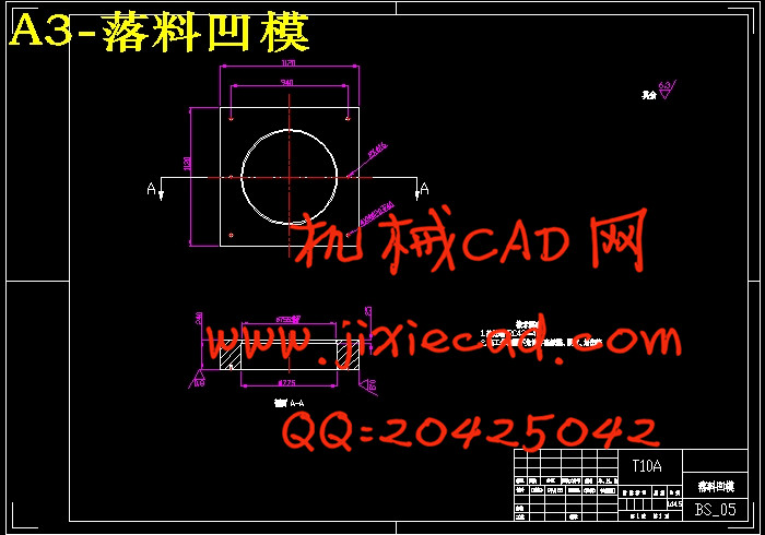
3.1落料工艺计算 10
3.1.1工艺性分析 10
3.1.2排样与搭边 10
3.1.3冲压力计算 10
3.1.4压力中心计算 11
3.1.5冲裁间隙 11
3.1.6凸、凹模刃口尺寸计算 11
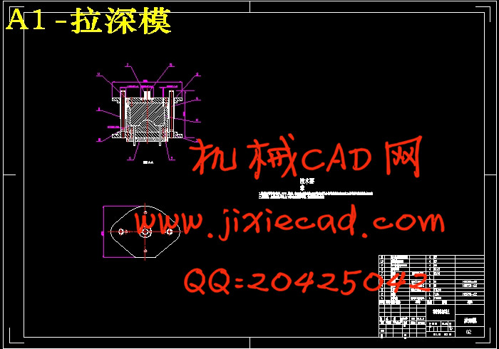
3.2拉深工艺计算 12
3.2.1拉深毛坯的确定 12
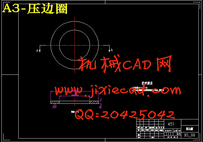
3.2.2判断是否采用压边圈 13
3.2.3拉深工艺计算 13
3.2.4确定各次拉深凸、凹模圆角半径及筒壁高度 14
3.2.5凸、凹模间隙及刃口尺寸 15
3.2.6压边力和拉深力的计算 16
3.2.7拉深功的计算 17
3.3胀形工艺计算 18
3.4冲孔工艺计算 20
3.4.1端面孔工艺计算 20
3.4.2凸缘孔工艺计算 22
第四章 模具的结构与零件设计 25
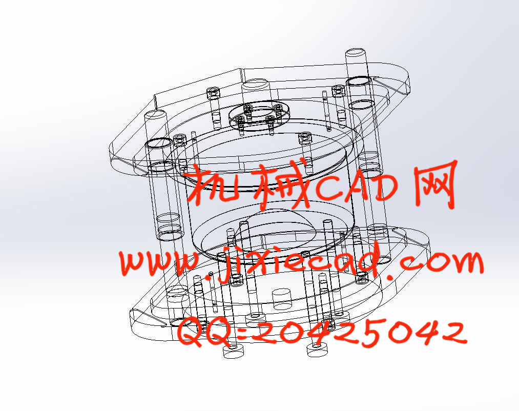
4.1模具的结构 25
4.2模具的工作原理 26
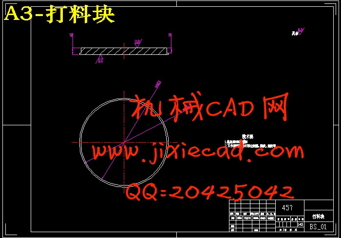
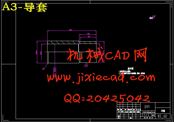
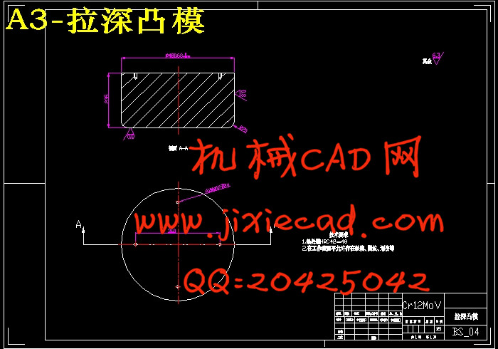
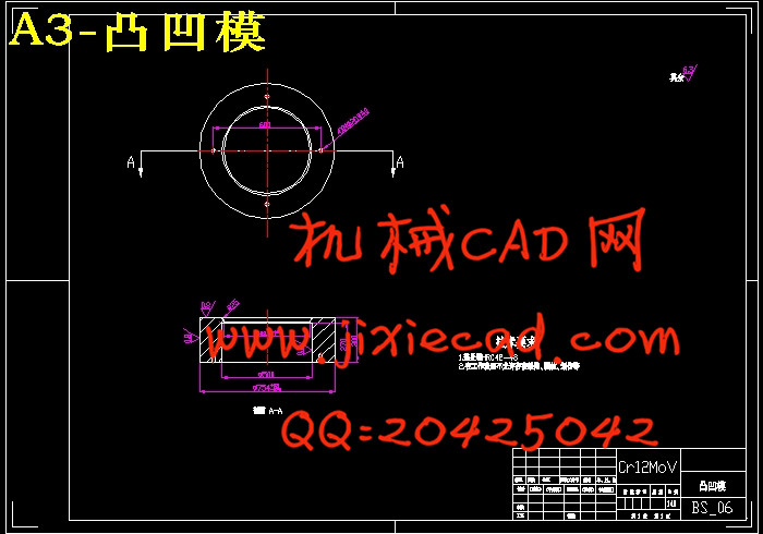
4.3模具主要零件设计 27
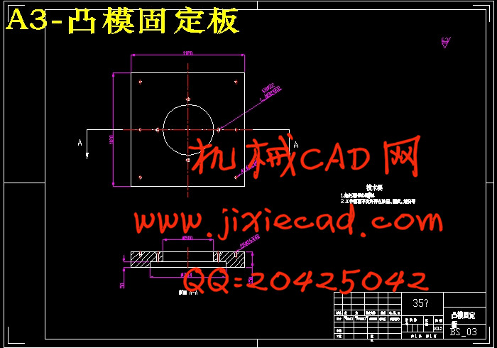
4.3.1工作零件设计 27
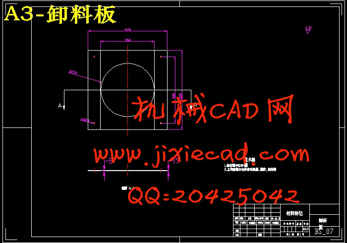
4.3.2卸料装置 30
4.3.3模架 31
4.3.4模柄 34
4.4冲压设备的选择 34
总结 36
致谢 38
参考文献 38
附录 39