设计简介
摘要
冷冲模是冲压加工工艺的装备之一,被广泛地运用在汽车、飞机、电机、仪表以及在国防工业中。冲压工艺具有生产效率高、生产成本低、材料利用率高、能成形复杂零件,适合大批量生产的优点,在某些领域已取代机械加工,并正逐步扩大其工艺范围。因此,冲压技术对发展生产、增强效率、更新产品等方面具有重要的作用。但同时,冲压技术的推广受到投入成本低,模具成本高,不适应中小生产规模的特点。但是总的说来,随着我国经济实力的进一步加强,模具行业,包括冷压模一定会得到更普及地应用
冷冲模的设计包括冲裁模设计、弯曲模设计、拉伸、胀形等模具的设计。冷冲模的设计也用到材料学、机械设计、工程材料、特种加工等方面的知识。因此它是一门综合性很强的学科。
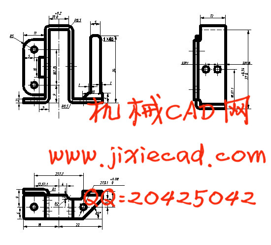
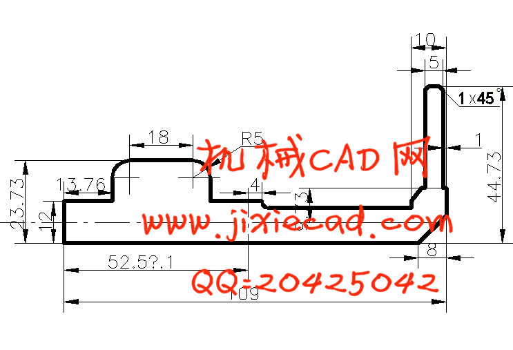
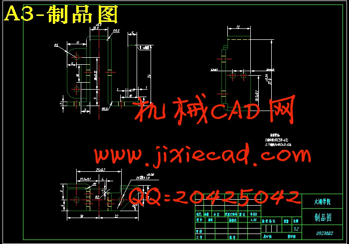
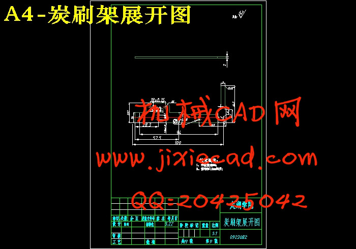
电机碳刷架的加工包括了冲孔、落料、和弯曲的加工。通过对冲孔模、落料模、弯曲模的学习,分析和比较了各加工工艺方案,完成了模具总体的结构分析,进行毛坯尺寸、排样、工序尺寸、冲压压力、压力中心、模具工作部分尺寸等工艺计算。绘制了装配草图并进行零部件初步选用设计,然后确定外形尺寸,选择冲压设备,绘制总的装配图和非标准的零件图。
在冲压模的设计过程中,还必须考虑到模具的成本,因此在进行选材,结构设计时,必须尽量不去设计形状复杂的结构,同时采用镶嵌式代替整体式的结构。针对模具的定位要求高的特点,在零件的设计中必须要有比较高的加工精度要求。总的一句话,必须在有高的模具寿命和满足加工精度要求的基础上,尽量降低模具材料的成本,简化模具的结构,这样才能有利于这个行业在我国的发展。
关键词:冲孔模、落料模、弯曲模、尺寸、冲裁模、装配图
Abstract
冷冲模是冲压加工工艺的装备之一,被广泛地运用在汽车、飞机、电机、仪表以及在国防工业中。冲压工艺具有生产效率高、生产成本低、材料利用率高、能成形复杂零件,适合大批量生产的优点,在某些领域已取代机械加工,并正逐步扩大其工艺范围。因此,冲压技术对发展生产、增强效率、更新产品等方面具有重要的作用。但同时,冲压技术的推广受到投入成本低,模具成本高,不适应中小生产规模的特点。但是总的说来,随着我国经济实力的进一步加强,模具行业,包括冷压模一定会得到更普及地应用
冷冲模的设计包括冲裁模设计、弯曲模设计、拉伸、胀形等模具的设计。冷冲模的设计也用到材料学、机械设计、工程材料、特种加工等方面的知识。因此它是一门综合性很强的学科。
电机碳刷架的加工包括了冲孔、落料、和弯曲的加工。通过对冲孔模、落料模、弯曲模的学习,分析和比较了各加工工艺方案,完成了模具总体的结构分析,进行毛坯尺寸、排样、工序尺寸、冲压压力、压力中心、模具工作部分尺寸等工艺计算。绘制了装配草图并进行零部件初步选用设计,然后确定外形尺寸,选择冲压设备,绘制总的装配图和非标准的零件图。
在冲压模的设计过程中,还必须考虑到模具的成本,因此在进行选材,结构设计时,必须尽量不去设计形状复杂的结构,同时采用镶嵌式代替整体式的结构。针对模具的定位要求高的特点,在零件的设计中必须要有比较高的加工精度要求。总的一句话,必须在有高的模具寿命和满足加工精度要求的基础上,尽量降低模具材料的成本,简化模具的结构,这样才能有利于这个行业在我国的发展。
关键词:冲孔模、落料模、弯曲模、尺寸、冲裁模、装配图
Abstract
The Cold Stamping Die Design of the Brushless Motor
Abstract:Cold punching mould that is used extensively among the all kinds die ,including punching hole mould, blanking die, bending mould, crooked model, conical die etc., The application of the cold punching die is more and more extensive in recent years. It is with low costs that there is the cold punchingly, product quality is steady, can process many kinds of performance , Part of the state. Its application and generallying receive the restriction in life-span of the mould and production safety,etc. at the same time . Author of this text proceed from rationality of the craft, analyse electrical machinery charcoal pastes up the structure of the shelf , Precision characteristic, and the control point in the course of processing, Consider and economize cost confirm electrical machinery charcoal brush blanking that shelf optimizes most process the process fully on the basis of satisfying the machining accuracy; And then pass the processing characteristic familiar with all kinds of moulds and inside structure, Finish the ensemble architecture analysis of the mould ; Author carry on blank size, arrange kind, process size, punching pressure, pressure in the center afterwards, mould work some size,etc. craft calculate, Strive to design the structure of every part of the mould and assembly relation with the best cost performance, Confirm the appearance of the mould on this basis, has finished the installation diagram and non-standard part picture. Confirm the type of the press and main parameter finally.
Keyword: punching hole mould;blanking die;bending mould;punching press;punching machine.
Keyword: mould;blanking die;bending mould;punching press;punching machine
目录
1 前言 ……………………………………………………………………………………………i
1.1 选题研究意义 ………………………………………………………………………… ii
2.确定工件的工序方案 ……………………………………………………………1
2,1长度方向的计算……………………………………………………………2
2.2宽度方向的计算 …………………………………………………………… 2
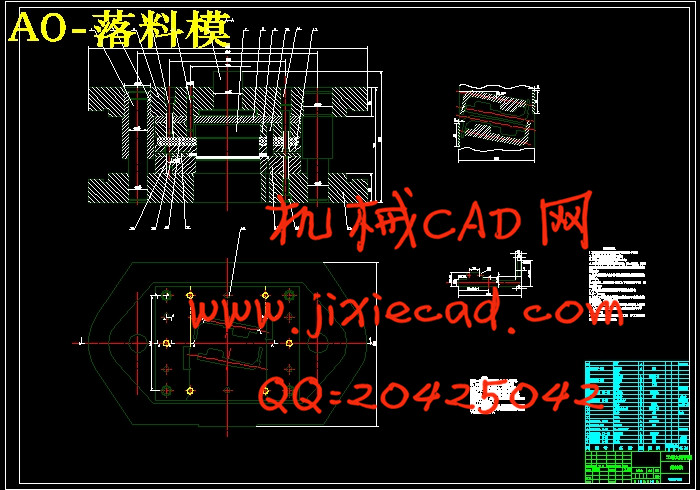
3.落料模的设计 ……………………………………………………………………2
3.1 冲裁件的工艺性…………………………………………………………… 2
3.2 冲裁间隙
3.3 凸凹模工作尺寸制造公差的确定.
3.3.1 3.3.1凸凹模尺寸计算应遵循如下原则:………………………………3
3.3.2 凸凹模的工作尺寸的计算:………………………………………………4
3.4 冲裁力、卸料力和推件力的计算:
3.4.1冲裁力的计算………………………………………… ………………….5
3.4.2 计算推件力F推:……………………………………………………… 5
3.4.3 计算卸料力F卸:………………………………………………………6
3.5确定压力中心 排样、搭边与料宽
3.5.1 排样………………………………………………………………………7
3.5.2 搭边……………………………………………………………………… 7
3.5.3 条料宽度的确定………………………………………………………… 8
3.6 凸、凹模的设计
3.6.1 凸模的设计……………………………………………………………… 9
3.6.a 凸模强度……………………………………………………………… 10
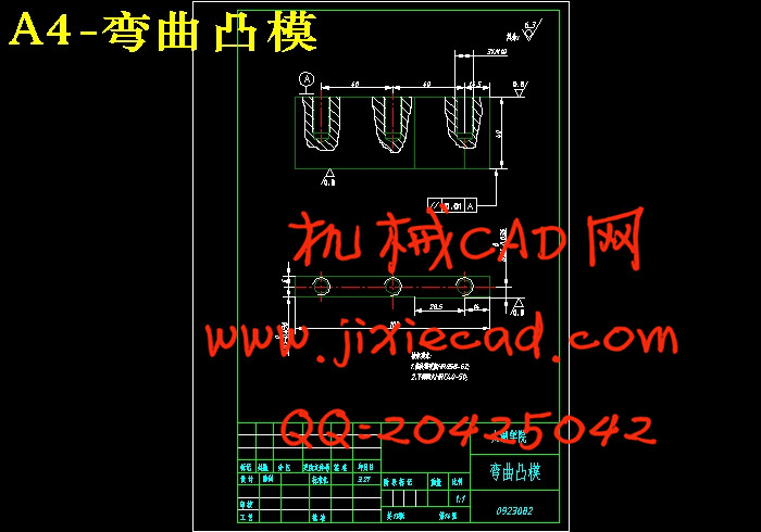
3.6.b压弯凸模的设计
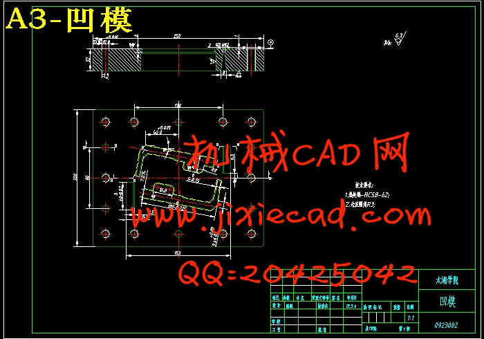
3.6.2 凹模的设计………………………………………………………………11
a.凹模的刃口形式………………………………………………………………11
b.凹模的外形及尺寸……………………………………………………………12
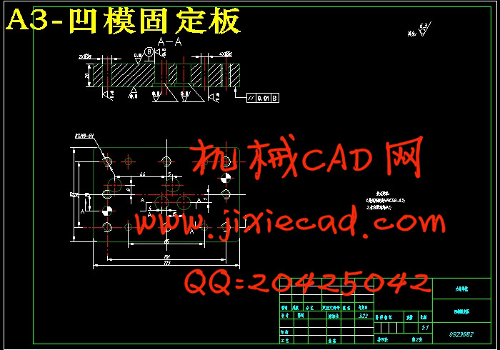
3.6.3 凸凹模的固定方法
a.凸模的固定……………………………………………………………………12
b.凹模的固定……………………………………………………………………12
3.7 定位零件的设计与选用
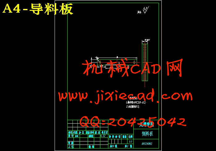
3.7.1.导料板的选用………………………………………………………… 12
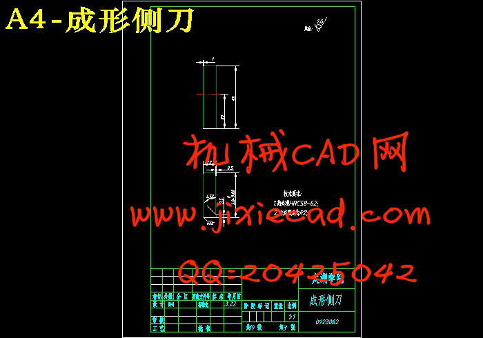
3.7.2.侧刃的选择…………………………………………………………… 12
1.1 选题研究意义 ………………………………………………………………………… ii
2.确定工件的工序方案 ……………………………………………………………1
2,1长度方向的计算……………………………………………………………2
2.2宽度方向的计算 …………………………………………………………… 2
3.落料模的设计 ……………………………………………………………………2
3.1 冲裁件的工艺性…………………………………………………………… 2
3.2 冲裁间隙
3.3 凸凹模工作尺寸制造公差的确定.
3.3.1 3.3.1凸凹模尺寸计算应遵循如下原则:………………………………3
3.3.2 凸凹模的工作尺寸的计算:………………………………………………4
3.4 冲裁力、卸料力和推件力的计算:
3.4.1冲裁力的计算………………………………………… ………………….5
3.4.2 计算推件力F推:……………………………………………………… 5
3.4.3 计算卸料力F卸:………………………………………………………6
3.5确定压力中心 排样、搭边与料宽
3.5.1 排样………………………………………………………………………7
3.5.2 搭边……………………………………………………………………… 7
3.5.3 条料宽度的确定………………………………………………………… 8
3.6 凸、凹模的设计
3.6.1 凸模的设计……………………………………………………………… 9
3.6.a 凸模强度……………………………………………………………… 10
3.6.b压弯凸模的设计
3.6.2 凹模的设计………………………………………………………………11
a.凹模的刃口形式………………………………………………………………11
b.凹模的外形及尺寸……………………………………………………………12
3.6.3 凸凹模的固定方法
a.凸模的固定……………………………………………………………………12
b.凹模的固定……………………………………………………………………12
3.7 定位零件的设计与选用
3.7.1.导料板的选用………………………………………………………… 12
3.7.2.侧刃的选择…………………………………………………………… 12
3.8 模架的尺寸和结构形式
3.8.1 模架的结构形式…………………………………………………………12
3.8.2 模架的尺寸………………………………………………………………12
3.9 卸料零件
3.9.1 卸料板的选择……………………………………………………………13
3.9.2 卸料螺钉…………………………………………………………………13
3.9.3 弹压装置的选用…………………………………………………………13
3.10 压力机的选择
3.10.1 压力机的公称压力…………………………………………………… 13
3.10.2 压力机的各参数选择………………………………………………… 13
3.11 导向零件……………………………………………………………………. 13
3.12 落料模的说明……………………………………………………………… 14
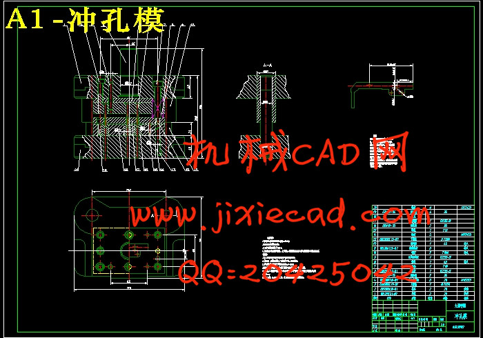
4 冲孔模的设计
4.1 冲裁件的工艺性………………………………………………………………14
4.1 冲裁件的工艺性 ………………………………………………………… 14
4.1.1 冲裁体的尺寸精度和断面粗糙度……………………………………… 14
4.2 冲裁间隙 …………………………………………………………………… 14
4.3 凸凹模工作部分尺寸与公差 ……………………………………………… 15
4.3.1 冲孔部分刃口计算 ………………………………………………………15
4.3.2 用配合加工法的尺寸计算 ………………………………………………15
4.5冲裁工艺力的确定 …………………………………………………………… 15
4.5 冲模的压力中心的确定……………………………………………………… 16
4.6 定位装置……………………………………………………………………… 16
4.7 卸料装置……………………………………………………………………… 16
4.7.1 弹压卸料板的设计………………………………………………………16
4.7.2 卸料螺钉的结构形式卸料螺钉的设计………………………………… 17
4.7.3 卸料板弹簧安装方法与有关尺寸……………………………………… 17
4.8 漏料孔………………………………………………………………………… 18
4.9 模架的结构形式和有关尺寸………………………………………………… 18
4.9.1 模架的有关尺寸………………………………………………………… 18
4.10 导向零件……………………………………………………………………. 18
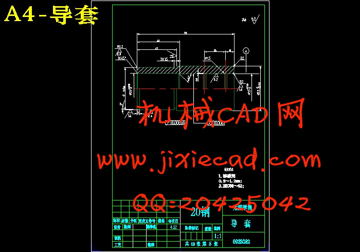
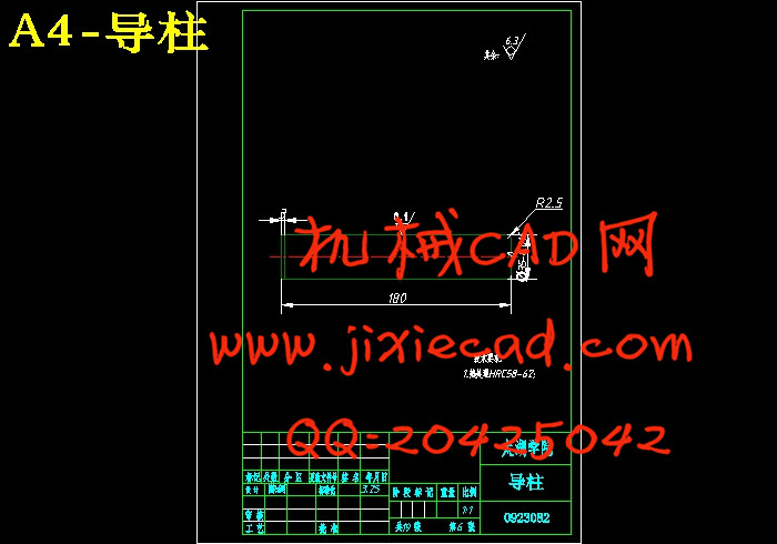
4.10.1 导柱、导套的尺寸结构………………………………………………… 19
4.10.2 导料销的选择……………………………………………………………19
4.10.3 螺钉及销钉的选择…………………………………………………… 19
4.11压力机的选择与模具的安装…………………………………………………19
4.11.1 作用在模柄上的冲裁力必须不小于P…………………………………20
4.11.2 各压力机的各参数选择…………………………………………………20
4.11.3 模具的安装………………………………………………………………20
4.12 说明
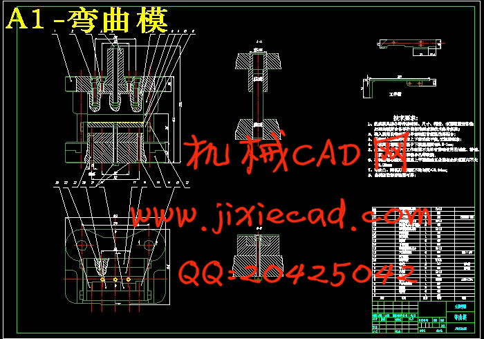
5 第一道弯曲模设计……………………………………………………………… 21
5.1 弯曲件的工艺性 ……………………………………………………………21
5.1.1 最小弯曲半径…………………………………………………………….21
5.1.2 弯曲件的直边高度……………………………………………………… 21
3.8.1 模架的结构形式…………………………………………………………12
3.8.2 模架的尺寸………………………………………………………………12
3.9 卸料零件
3.9.1 卸料板的选择……………………………………………………………13
3.9.2 卸料螺钉…………………………………………………………………13
3.9.3 弹压装置的选用…………………………………………………………13
3.10 压力机的选择
3.10.1 压力机的公称压力…………………………………………………… 13
3.10.2 压力机的各参数选择………………………………………………… 13
3.11 导向零件……………………………………………………………………. 13
3.12 落料模的说明……………………………………………………………… 14
4 冲孔模的设计
4.1 冲裁件的工艺性………………………………………………………………14
4.1 冲裁件的工艺性 ………………………………………………………… 14
4.1.1 冲裁体的尺寸精度和断面粗糙度……………………………………… 14
4.2 冲裁间隙 …………………………………………………………………… 14
4.3 凸凹模工作部分尺寸与公差 ……………………………………………… 15
4.3.1 冲孔部分刃口计算 ………………………………………………………15
4.3.2 用配合加工法的尺寸计算 ………………………………………………15
4.5冲裁工艺力的确定 …………………………………………………………… 15
4.5 冲模的压力中心的确定……………………………………………………… 16
4.6 定位装置……………………………………………………………………… 16
4.7 卸料装置……………………………………………………………………… 16
4.7.1 弹压卸料板的设计………………………………………………………16
4.7.2 卸料螺钉的结构形式卸料螺钉的设计………………………………… 17
4.7.3 卸料板弹簧安装方法与有关尺寸……………………………………… 17
4.8 漏料孔………………………………………………………………………… 18
4.9 模架的结构形式和有关尺寸………………………………………………… 18
4.9.1 模架的有关尺寸………………………………………………………… 18
4.10 导向零件……………………………………………………………………. 18
4.10.1 导柱、导套的尺寸结构………………………………………………… 19
4.10.2 导料销的选择……………………………………………………………19
4.10.3 螺钉及销钉的选择…………………………………………………… 19
4.11压力机的选择与模具的安装…………………………………………………19
4.11.1 作用在模柄上的冲裁力必须不小于P…………………………………20
4.11.2 各压力机的各参数选择…………………………………………………20
4.11.3 模具的安装………………………………………………………………20
4.12 说明
5 第一道弯曲模设计……………………………………………………………… 21
5.1 弯曲件的工艺性 ……………………………………………………………21
5.1.1 最小弯曲半径…………………………………………………………….21
5.1.2 弯曲件的直边高度……………………………………………………… 21
5.1.3 弯曲件孔边距离………………………………………………………… 21
5.1.4 弯曲件的精度…………………………………………………………… 21
5.2 弯曲件的回弹
5.2.1 影响回弹的因素……………………………………………………… 21
5.2.2 回弹角的大小…………………………………………………………… 21
5.2.3 减少回弹角的措施……………………………………………………… 21
5.3 弯曲力的计算
5.3.1 弯曲力的大小…………………………………………………………… 22
5.3.3 弯曲时压力机公称压力的确定………………………………………… 22
5.4 弯曲模的间隙
5.5 弯曲模工作部分尺寸计算 ………………………………………………… 23
5.5.1 凸模圆角半径…………………………………………………………… 23
5.5.2 凹模圆角半径…………………………………………………………… 23
5.5.3 凸、凹模工作部分的尺寸与公差……………………………………… 23
5.6 压力机的选择
5.6.1 压力机的公称压力……………………………………………………… 23
5.6.2 压力机各参数…………………………………………………………… 23
5.7 模架的设计与有关尺寸
5.7.1 模架的结构形式………………………………………………………… 24
5.7.2 模架的有关尺寸………………………………………………………… 24
5.8 导向零件
5.8.1 导柱、导套的尺寸、结构…………………………………………… …14
5.9 顶出机构
5.9.1 顶板与凹模的配合……………………………………………………….25
5.9.2 顶板的尺寸……………………………………………………………… 25
5.10 模具的安装
5.10.1 模具安装的注意事项………………………………………………… 26
5.10.2 模具安装的一般次序………………………………………………… 26
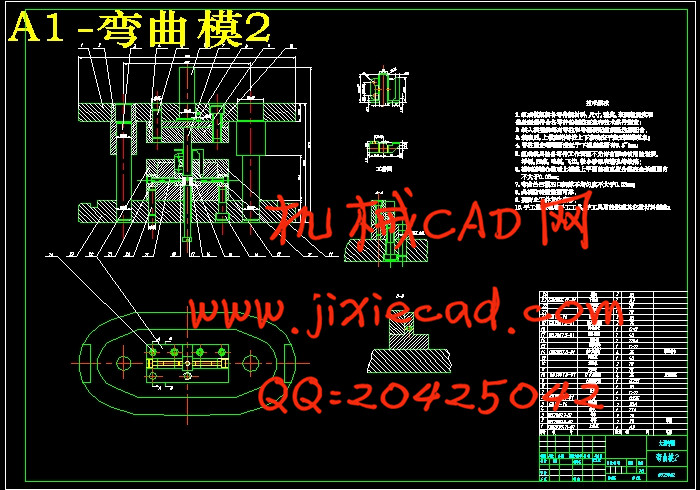
6 最后一道弯曲模设计
6.1 弯曲件的工艺性…………………………………………………………… 27
6.1.1 弯曲件如图所示:……………………………………………………… 27
6.1.2 最小弯曲半径…………………………………………………………… 27
6.1.3 弯曲件直边高度………………………………………………………… 27
6.1.4 弯曲件的精度…………………………………………………………… 27
6.2 弯曲件的回弹.
6.2.1 影响回弹的因素………………………………………………………… 28
6.2.2 回弹角的大小…………………………………………………………… 28
6.2.3 减小回弹的措施………………………………………………………… 28
6.3 弯曲力的计算
6.3.1 弯曲力的大小通常采用经验公式……………………………………… 28
6.3.2 顶件力或压料力F1………………………………… ……………………29
6.3.3 弯曲时压力机公称压力的确定…………………………………………295.1.4 弯曲件的精度…………………………………………………………… 21
5.2 弯曲件的回弹
5.2.1 影响回弹的因素……………………………………………………… 21
5.2.2 回弹角的大小…………………………………………………………… 21
5.2.3 减少回弹角的措施……………………………………………………… 21
5.3 弯曲力的计算
5.3.1 弯曲力的大小…………………………………………………………… 22
5.3.3 弯曲时压力机公称压力的确定………………………………………… 22
5.4 弯曲模的间隙
5.5 弯曲模工作部分尺寸计算 ………………………………………………… 23
5.5.1 凸模圆角半径…………………………………………………………… 23
5.5.2 凹模圆角半径…………………………………………………………… 23
5.5.3 凸、凹模工作部分的尺寸与公差……………………………………… 23
5.6 压力机的选择
5.6.1 压力机的公称压力……………………………………………………… 23
5.6.2 压力机各参数…………………………………………………………… 23
5.7 模架的设计与有关尺寸
5.7.1 模架的结构形式………………………………………………………… 24
5.7.2 模架的有关尺寸………………………………………………………… 24
5.8 导向零件
5.8.1 导柱、导套的尺寸、结构…………………………………………… …14
5.9 顶出机构
5.9.1 顶板与凹模的配合……………………………………………………….25
5.9.2 顶板的尺寸……………………………………………………………… 25
5.10 模具的安装
5.10.1 模具安装的注意事项………………………………………………… 26
5.10.2 模具安装的一般次序………………………………………………… 26
6 最后一道弯曲模设计
6.1 弯曲件的工艺性…………………………………………………………… 27
6.1.1 弯曲件如图所示:……………………………………………………… 27
6.1.2 最小弯曲半径…………………………………………………………… 27
6.1.3 弯曲件直边高度………………………………………………………… 27
6.1.4 弯曲件的精度…………………………………………………………… 27
6.2 弯曲件的回弹.
6.2.1 影响回弹的因素………………………………………………………… 28
6.2.2 回弹角的大小…………………………………………………………… 28
6.2.3 减小回弹的措施………………………………………………………… 28
6.3 弯曲力的计算
6.3.1 弯曲力的大小通常采用经验公式……………………………………… 28
6.3.2 顶件力或压料力F1………………………………… ……………………29
6.4 弯曲模的间隙
6.5 弯曲模工作部分尺寸计算.
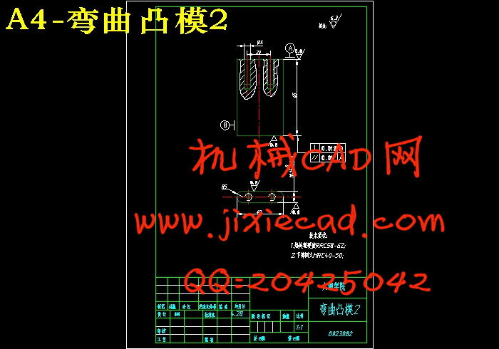
6.5.1 凸模圆角半径rp…………………………………………………………29
6.5.2 凹模圆角半径rd及凹模深度L…………………………………………29
6.5.3 凸、凹模工作部分的尺寸公差………………………………………… 29
6.6 压力机的选择…………………………………………………………………30
6.7 模架的设计与有关尺寸………………………………………………………30
6.8 顶出机构…………….……………………………………………………… 30
6.9 模具的安装……………………………………………………………………31
6.9.1模具安装的注意事项 …………………………………………………… 31
6.9.2 模具安装的一般次序 …………………………………………………… 31
7. 结论与展望 …………………………………………………………………… 32
8. 致谢 …………………………………………………………………………… 33
9. 参考文献 ……………………………………………………………………… 34