设计简介
摘要
模具属于精密机械的产品,它主要机械零件和机构组成。如成形工作零件、导向零件、定位零件、支撑零件及送料机构、抽芯机构、推出机构等。模具与相应的成形设备(如冲床、塑料注射机、压铸机等)配套使用时,可直接改变金属或非金属材料的形状、尺寸、相对位置和性能,使之成形为合格的制件。在文档中第一部分,主要叙述了冲压模具的发展状况,说明了冲压模具的重要性与本次设计的意义,接着是对冲压件的工艺分析,完成了工艺方案的确定。第二部分,对零件排样图的设计,完成了材料利用率的计算。再进行冲裁工艺力的计算和冲裁模工作部分的设计计算,对选择冲压设备提供依据。最后对主要零部件的设计和标准件的选择,为本次设计模具的绘制和模具的成形提供依据,以及为装配图各尺寸提供依据。通过前面的设计方案画出模具各零件图和装配图。
关键词:模具设计;复合模
Abstract
Mold products are precision machinery, it mainly consists of mechanical parts and bodies,such as forming working parts, parts orientation, positioning parts, supporting parts, positioning components and feed mechanism, core-pulling mechanism, introduced institutions. Mold and the corresponding forming equipment supporting the use of, may directly alter the shape of metal or non-metallic materials, size, relative position and performance, shaping the work piece for qualified.In the first part of the document mainly describes the development of stamping die, stamping die illustrate the importance and significance of this design, and then stamping parts of the process analysis, completed a process to identify programs. The second part of the nesting parts of the design plans to complete the calculation of the utilization of the material further edge blanking process of calculation and Die Design and Calculation of the work of some of the stamping equipment to provide a basis to choose. Finally, the main components of standard design and the choice of design-based mapping tool and provide a basis for forming mold, as well as the assembly drawing to provide the basis of the size. Through the draw in front of mold design and assembly of the parts diagram Fig.
目录
摘要 2
Abstract 3
1.绪论 6
1.1 模具研究的意义 6
1.2 冲压技术的发展 6
1.3 冲压工艺的基本工序和分类 7
1.4 冲压成型的特点 7
1.5 此次冲压模具设计的目的和意义 8
2 零件冲压工艺分析 9
2.1 材料工艺性分析 9
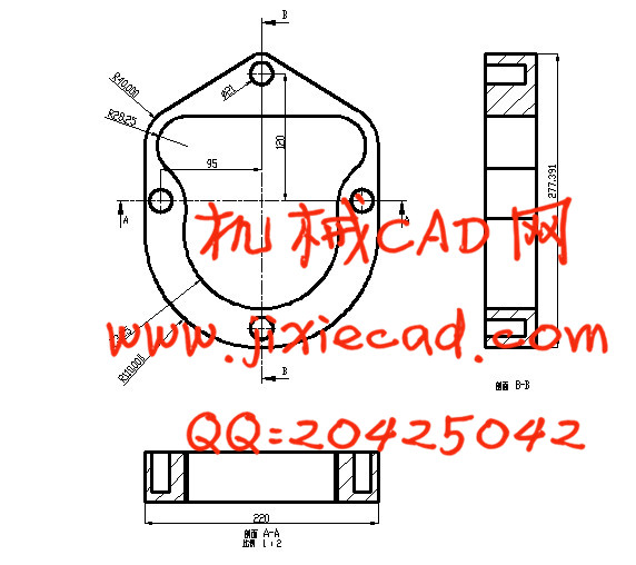
2.2 零件结构 10
2.3 尺寸精度分析 10
2.4 分析制造零件所需方案 10
2.5 方案的比较 10
2.6 方案的确定 10
2.7 工序的确定 11
3 工艺计算 13
3.1 排样的设计与计算 13
3.1.1 毛坯形状的确定 13
3.1.2 毛坯尺寸确定 13
3.1.3 确定搭边 14
3.1.4 确定条料宽度 14
3.1.5 确定条料的进距 15
3.1.6 材料的利用率 15
3.1.7 排样图 15
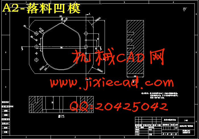
3.2落料的相关计算 16
3.2.1 落料所需冲裁力、卸料力、顶件力、推件力的确定 16
3.2.2 冲裁模刃口尺寸计算 17
3.3 拉深相关计算 19
3.3.1 拉深次数的确定 19
3.3.2 拉深所需拉深力、压料力、弯曲力、翻边力的计算 20
3.3.3 拉深模工作部分尺寸计算 21
3.4 压力中心的确定 22
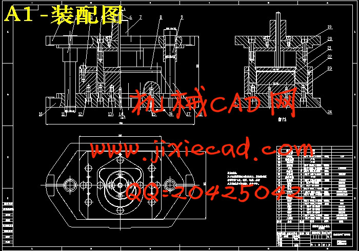
4 模具结构与零件的设计 23
4.1 模具结构形式的确定 23
4.2 模具零件的设计 24
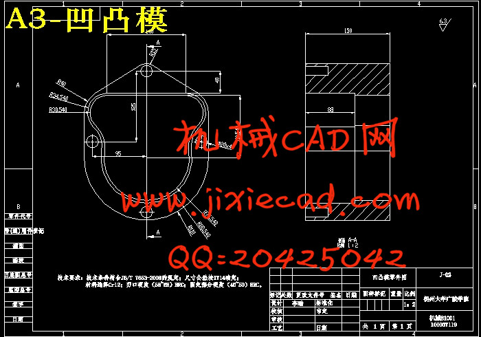
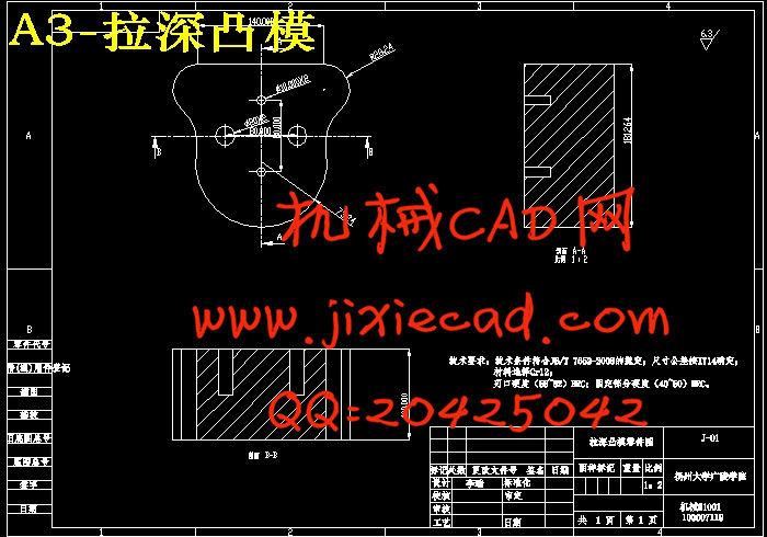
4.2.1 凸模、凹模的确定 24
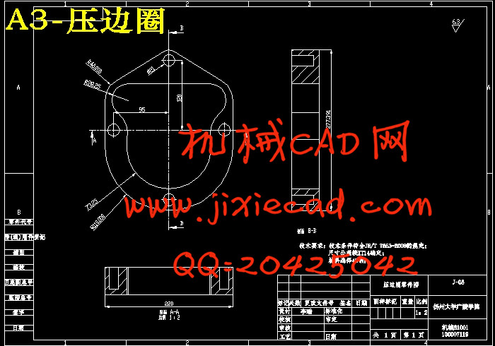
4.2.2 压边圈的确定 25
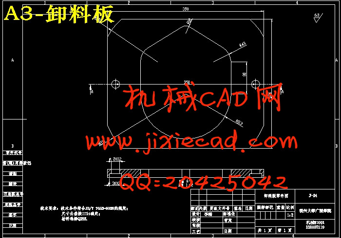
4.2.3 卸料版的确定 25
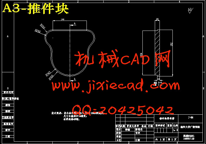
4.2.4 推件块的确定 25
4.2.5 定位零件的选择 26
4.2.6 紧固零件的选择 26
4.2.7 模架的选择 26
4.2.8 导向零件的选择 27
4.2.9 模柄的选择 27
4.3 凸模、凹模高度及强度校核 27
4.3.1 高度确定 27
4.3.2 强度校核 28
4.3.3 确定模具的总高度 29
4.4 绘制模具装配图及非标准件零件图 29
5 使用SoildWorks绘制三维图 30
6 设计总结 31
7 参考文献 33