设计简介
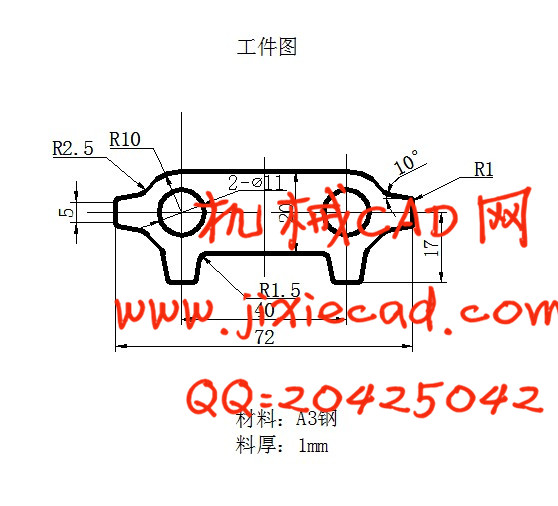
齿轮螺栓垫片冲压成形工艺与模具设计
摘 要
本设计题目为齿轮螺栓垫片冲压成形工艺与模具设计,体现了板类冲压零件的设计要求、内容及方向,有一定的设计意义。通过对该零件模具的设计,进一步加强了设计者冲压模具设计的基础知识,为设计更复杂的冲压模具做好了铺垫并吸取了更深刻的经验。
本设计运用冲压成型工艺及模具设计的基础知识,首先分析了工件的成形工艺及模具成形结构对制件质量的影响。介绍了齿轮螺栓垫片冲压模具设计时要注意的要点,通过对制件进行工艺分析,可确定制件的成形加工用一套复合模即可。从控制制件尺寸精度出发,对齿轮螺栓垫片冲压模具的各主要尺寸进行了理论计算,以确定各工作零件的尺寸,从模具设计到零部件的加工工艺以及装配工艺等进行详细的阐述,并应用CAD进行各重要零件的设计。
关键词:复合模;工艺分析;模具零部件的加工工艺。
Gear bolt gasket stamping process and die design
Abstract
The topic of this design is the gear bolt pad stamps forming handicraft and design for die.The requirement,content and direction of the design of the stamps forming plate parts are embodied on this stamping die design. The designer’s foundation knowledge of the stamping die design is reinforced and is able to design more complex stamping die through the design.
This design the elementary knowledge which designs using the stamping formation craft and the die, first has analyzed the work piece formed craft and the die forming structure to the workpiece quality influence. Introduced the gear bolt filling piece stamping die design when must pay attention to the main point, through carries on the craft analysis to the workpiece, may determine the workpiece the formed processing uses set of superposable dies. Embarks from the control workpiece size precision, counter gear bolt filling piece stamping die each main dimension has carried on the theoretical calculation, by determined each work components the size, designs from the die to the spare part processing craft as well as the assembly craft and so on carries on the detailed elaboration, and carries on each important components using CAD the design.
Key words: compound die;process analysis;processing of die parts.
目 录
1 绪 论 1
2 零件的工艺性分析 3
2.1 零件的总体分析 3
2.1.1外形落料的工艺性 3
2.1.2冲孔的工艺性 3
2.1.3冲裁件的孔边距和孔间距 4
2.1.4尺寸精度 4
3 工艺方案的确定 5
4 排样设计与计算 6
4.1确定搭边与搭肩值 6
4.2确定零件的排样方案 6
4.3计算送料步距和条料的宽度 7
4.4计算材料的利用率 7
5 计算冲压力和初选压力机 8
5.1冲裁工序总力的计算 8
5.2初选压力机 9
5.3 确定压力中心 10
6 模具结构形式的选择与确定 11
6.1 模具类型的选择 11
6.2定位方式的选择 11
6.3导向方式的选择 11
6.4 卸料方式 11
6.5 送料方式 11
7 模具工作零部件刃口尺寸的计算 12
7.1冲裁 孔的凸、凹模刃口尺寸的计算 12
7.2外形落料凸模、凹模刃口尺寸的计算 12
8 模具主要零部件设计 15
8.1工作零部件的结构设计 15
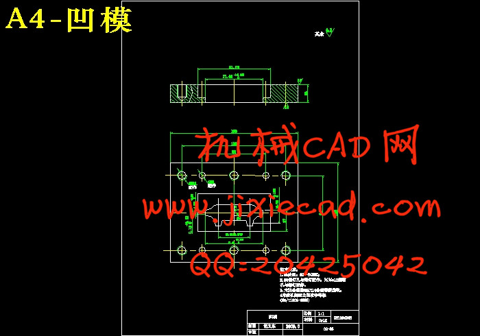
8.1.1落料凹模的设计 15
8.1.2 冲孔凸模的设计 16
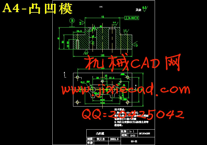
8.1.3落料凸模(凸凹模)的设计 19
8.2定位装置的设计与标准化 19
8.2.1挡料销及导料销的设计与标准化 19
8.2.2挡料销与导料销位置的确定 20
8.2.3导料销位置的确定 20
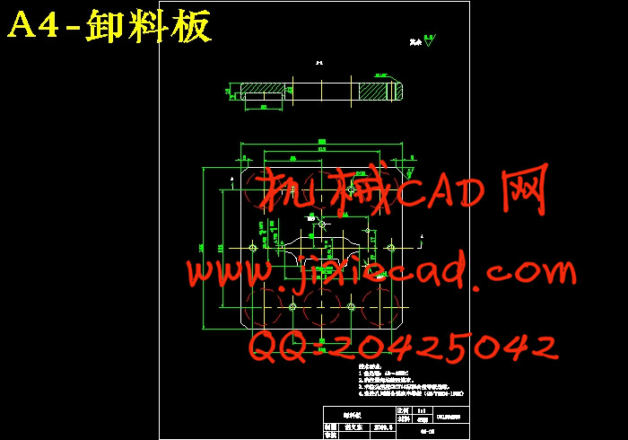
8.3卸料装置的设计及标准化 20
8.3.1弹性卸料板的结构形式 20
8.3.2卸料螺钉的选用 21
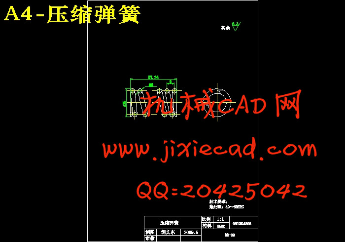
8.3.3卸料弹簧的设计及选用 21
8.4推件装置的设计与标准化 22
8.4.1刚性推件装置的设计与标准化 22
8.4.2推件块的设计 22
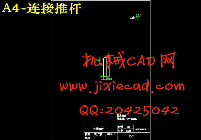
8.4.3连接推杆的选用 22
8.4.4推板的设计 22
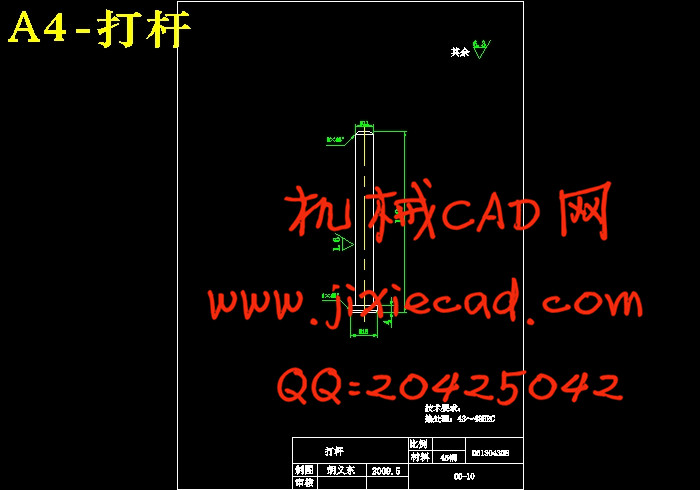
8.4.5打杆的设计 22
8.5支撑固定零件的设计与标准化 23
8.5.1模架的选用 23
8.5.2 凸模固定板的设计 23
8.6导向零件的设计与标准化 23
8.7紧固零件的设计与标准化 24
9 冲压设备的的选用 25
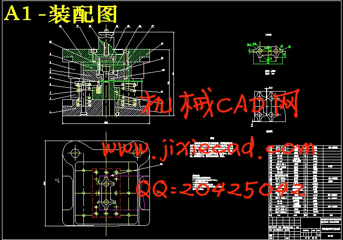
10 模具总装图 26
结束语 27
致 谢 28
参考文献 29
摘 要
本设计题目为齿轮螺栓垫片冲压成形工艺与模具设计,体现了板类冲压零件的设计要求、内容及方向,有一定的设计意义。通过对该零件模具的设计,进一步加强了设计者冲压模具设计的基础知识,为设计更复杂的冲压模具做好了铺垫并吸取了更深刻的经验。
本设计运用冲压成型工艺及模具设计的基础知识,首先分析了工件的成形工艺及模具成形结构对制件质量的影响。介绍了齿轮螺栓垫片冲压模具设计时要注意的要点,通过对制件进行工艺分析,可确定制件的成形加工用一套复合模即可。从控制制件尺寸精度出发,对齿轮螺栓垫片冲压模具的各主要尺寸进行了理论计算,以确定各工作零件的尺寸,从模具设计到零部件的加工工艺以及装配工艺等进行详细的阐述,并应用CAD进行各重要零件的设计。
关键词:复合模;工艺分析;模具零部件的加工工艺。
Gear bolt gasket stamping process and die design
Abstract
The topic of this design is the gear bolt pad stamps forming handicraft and design for die.The requirement,content and direction of the design of the stamps forming plate parts are embodied on this stamping die design. The designer’s foundation knowledge of the stamping die design is reinforced and is able to design more complex stamping die through the design.
This design the elementary knowledge which designs using the stamping formation craft and the die, first has analyzed the work piece formed craft and the die forming structure to the workpiece quality influence. Introduced the gear bolt filling piece stamping die design when must pay attention to the main point, through carries on the craft analysis to the workpiece, may determine the workpiece the formed processing uses set of superposable dies. Embarks from the control workpiece size precision, counter gear bolt filling piece stamping die each main dimension has carried on the theoretical calculation, by determined each work components the size, designs from the die to the spare part processing craft as well as the assembly craft and so on carries on the detailed elaboration, and carries on each important components using CAD the design.
Key words: compound die;process analysis;processing of die parts.
目 录
1 绪 论 1
2 零件的工艺性分析 3
2.1 零件的总体分析 3
2.1.1外形落料的工艺性 3
2.1.2冲孔的工艺性 3
2.1.3冲裁件的孔边距和孔间距 4
2.1.4尺寸精度 4
3 工艺方案的确定 5
4 排样设计与计算 6
4.1确定搭边与搭肩值 6
4.2确定零件的排样方案 6
4.3计算送料步距和条料的宽度 7
4.4计算材料的利用率 7
5 计算冲压力和初选压力机 8
5.1冲裁工序总力的计算 8
5.2初选压力机 9
5.3 确定压力中心 10
6 模具结构形式的选择与确定 11
6.1 模具类型的选择 11
6.2定位方式的选择 11
6.3导向方式的选择 11
6.4 卸料方式 11
6.5 送料方式 11
7 模具工作零部件刃口尺寸的计算 12
7.1冲裁
7.2外形落料凸模、凹模刃口尺寸的计算 12
8 模具主要零部件设计 15
8.1工作零部件的结构设计 15
8.1.1落料凹模的设计 15
8.1.2 冲孔凸模的设计 16
8.1.3落料凸模(凸凹模)的设计 19
8.2定位装置的设计与标准化 19
8.2.1挡料销及导料销的设计与标准化 19
8.2.2挡料销与导料销位置的确定 20
8.2.3导料销位置的确定 20
8.3卸料装置的设计及标准化 20
8.3.1弹性卸料板的结构形式 20
8.3.2卸料螺钉的选用 21
8.3.3卸料弹簧的设计及选用 21
8.4推件装置的设计与标准化 22
8.4.1刚性推件装置的设计与标准化 22
8.4.2推件块的设计 22
8.4.3连接推杆的选用 22
8.4.4推板的设计 22
8.4.5打杆的设计 22
8.5支撑固定零件的设计与标准化 23
8.5.1模架的选用 23
8.5.2 凸模固定板的设计 23
8.6导向零件的设计与标准化 23
8.7紧固零件的设计与标准化 24
9 冲压设备的的选用 25
10 模具总装图 26
结束语 27
致 谢 28
参考文献 29