设计简介
汽车消音器零件的冲压工艺及模具设计方案
摘 要
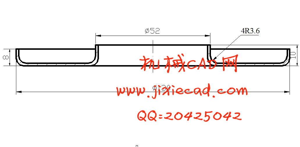
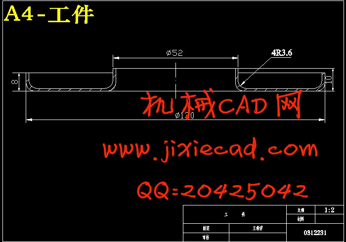
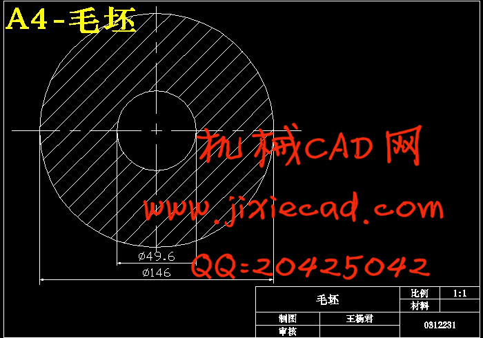
这次设计参考了一些冲压工艺资料具体见参考文献。文章分析了汽车消音器零件在批量生产条件下的冲压工艺及模具设计过程。该消音器零件采用翻边工艺(包括内翻边和外翻边)来完成,采用环形毛坯,只需要先进行内翻边,再进行外翻边工艺就可以得到消音器零件。该消音器零件的冲压工艺比较简单,工件结构对称,毛坯适合进行翻边工艺。
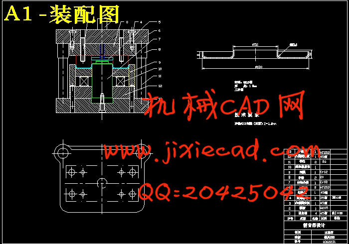
由于内翻和外翻两个工序都在同一个工位上完成,所以在选取模具时选择内外翻复合模。复合模的特点是内翻和外翻两个工序都在同一个工位上完成,生产率较高,生产出的制品的精度也较高,占用设备数量少。此工件简单对称,所以模具并不复杂,比其他方案要具有优越性。
这次设计受益匪浅,特别是通过毕业设计,让我能够把所学同工程实际相结合。这些经验能给自己今后的工作提供借鉴。
关键词 :消音器 冲压工艺 翻边
汽车消音器零件的冲压工艺及模具设计方案
Abstract
Introduced the automobile damper components ramming craft and the mold design,Succinctly has analyzed under the volume production condition its ramming technological process and the mold design main point. This damper components use the flange craft (including nearby in flange and eversion) complete. Uses the ring-like semifinished materials,In only needs to carry on the flange first,Again carries on nearby the eversion the craft to be possible to obtain the damper components. This damper components ramming craft quite is simple,The work piece structure is symmetrical,The semifinished materials suitablly carry on the flange craft. Because in turns with the eversion two working procedures both completes in the identical location,Inside and outside therefore when selects the mold chooses turns the superposable die. This graduation project was a great help to me. Specially through graduation project,Let me be able actual to study the same project to unify. These experiences will be able to give oneself the next work to provide the model.
keyword : punching press flanging
目录
绪论…………………………………………………………1
摘要…………………………………………………………1
1.中国模具工业的发展现状 …………………………………1
1.1国内模具的发展现状 ……………………………………………1
1.2 国外模具的发展现状 ………………………………………2
2.冲压工艺与方案…………………………………………………3
2.1 冲压件工艺性分析………………………………………………3
2.2冲压工艺方案的确定 ……………………………………………4
2.3毛皮尺寸计算及排样 ………………………………………5
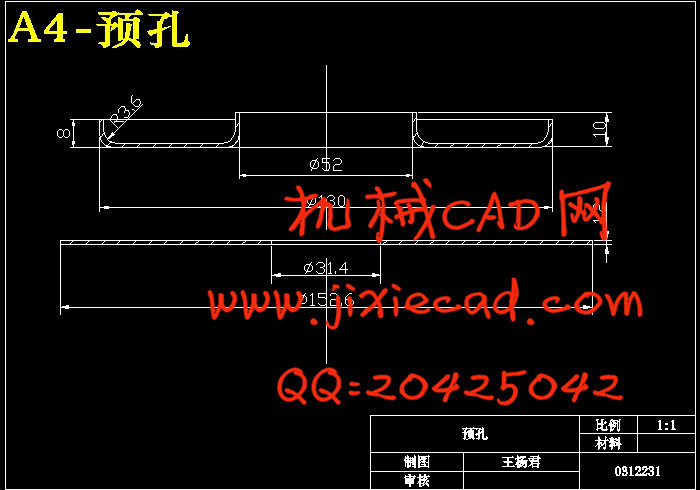
2.3.1毛坯的尺寸计算…………………………………………5
2.3.2排样……………………………………………………5
2.4工艺计算 ………………………………………………………6
2.4.1 内孔翻边……………………………………………………6
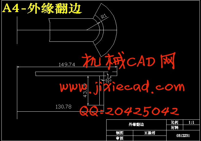
2.4.2 外缘翻边……………………………………………………6
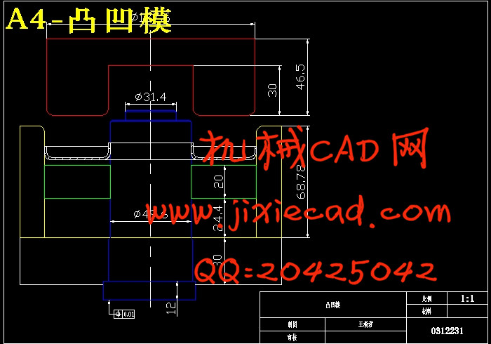
2.4.3 凸模与凹模直径的计算………………………………………8
2.5 翻边力与压力中心的计算,初选压力机 ………………………9
2.5.1 翻边力的计算 ………………………………………………9
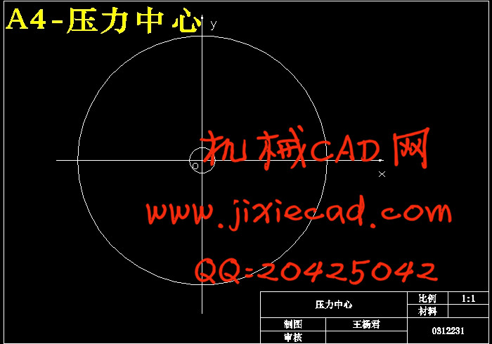
2.5.2 压力中心的确定 ……………………………………………10
2.5.3 工件零件刃口尺寸计算………………………………………10
2.5.4 卸料橡胶的设计 ……………………………………………11
3.模具结构形式的选择与确定 ……………………………12
3.1模具的整体设计 ……………………………………………12
3.1.1 模具类型的选择………………………………………………12
3.1.2 模具结构方式的确定 …………………………………………12
3.1.3 定位装置的选择………………………………………………12
3.1.4 导向方式 ……………………………………………………12
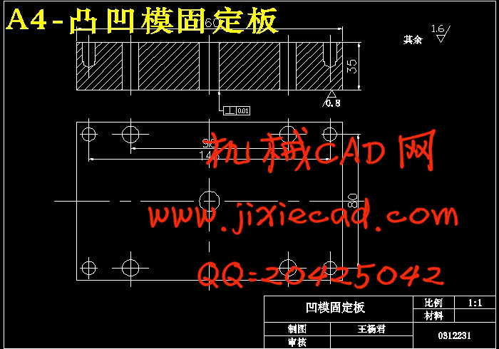
3.2主要零部件的设计……………………………………………12
3.2.1 工作零件的结构设计 …………………………………………12
3.2.2 凸凹模长度的计算 ……………………………………………12
3.3 其他零部件的确定……………………………………………13
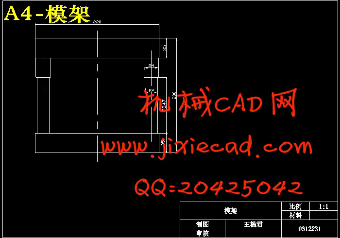
3.3.1 模架的选择……………………………………………………13
3.3.2 挡料板的尺寸规格 ……………………………………………14
3.3.3 联接件的选用 …………………………………………………14
4.模具总装 ………………………………………………15
4.1 装配图 …………………………………………………………15
4.2 压力机的选择与校核 ……………………………………………16
5.设计总结 ………………………………………………17
致谢 ……………………………………………………………19
参考文献 ………………………………………………………20
摘 要
这次设计参考了一些冲压工艺资料具体见参考文献。文章分析了汽车消音器零件在批量生产条件下的冲压工艺及模具设计过程。该消音器零件采用翻边工艺(包括内翻边和外翻边)来完成,采用环形毛坯,只需要先进行内翻边,再进行外翻边工艺就可以得到消音器零件。该消音器零件的冲压工艺比较简单,工件结构对称,毛坯适合进行翻边工艺。
由于内翻和外翻两个工序都在同一个工位上完成,所以在选取模具时选择内外翻复合模。复合模的特点是内翻和外翻两个工序都在同一个工位上完成,生产率较高,生产出的制品的精度也较高,占用设备数量少。此工件简单对称,所以模具并不复杂,比其他方案要具有优越性。
这次设计受益匪浅,特别是通过毕业设计,让我能够把所学同工程实际相结合。这些经验能给自己今后的工作提供借鉴。
关键词 :消音器 冲压工艺 翻边
汽车消音器零件的冲压工艺及模具设计方案
Abstract
Introduced the automobile damper components ramming craft and the mold design,Succinctly has analyzed under the volume production condition its ramming technological process and the mold design main point. This damper components use the flange craft (including nearby in flange and eversion) complete. Uses the ring-like semifinished materials,In only needs to carry on the flange first,Again carries on nearby the eversion the craft to be possible to obtain the damper components. This damper components ramming craft quite is simple,The work piece structure is symmetrical,The semifinished materials suitablly carry on the flange craft. Because in turns with the eversion two working procedures both completes in the identical location,Inside and outside therefore when selects the mold chooses turns the superposable die. This graduation project was a great help to me. Specially through graduation project,Let me be able actual to study the same project to unify. These experiences will be able to give oneself the next work to provide the model.
keyword : punching press flanging
目录
绪论…………………………………………………………1
摘要…………………………………………………………1
1.中国模具工业的发展现状 …………………………………1
1.1国内模具的发展现状 ……………………………………………1
1.2 国外模具的发展现状 ………………………………………2
2.冲压工艺与方案…………………………………………………3
2.1 冲压件工艺性分析………………………………………………3
2.2冲压工艺方案的确定 ……………………………………………4
2.3毛皮尺寸计算及排样 ………………………………………5
2.3.1毛坯的尺寸计算…………………………………………5
2.3.2排样……………………………………………………5
2.4工艺计算 ………………………………………………………6
2.4.1 内孔翻边……………………………………………………6
2.4.2 外缘翻边……………………………………………………6
2.4.3 凸模与凹模直径的计算………………………………………8
2.5 翻边力与压力中心的计算,初选压力机 ………………………9
2.5.1 翻边力的计算 ………………………………………………9
2.5.2 压力中心的确定 ……………………………………………10
2.5.3 工件零件刃口尺寸计算………………………………………10
2.5.4 卸料橡胶的设计 ……………………………………………11
3.模具结构形式的选择与确定 ……………………………12
3.1模具的整体设计 ……………………………………………12
3.1.1 模具类型的选择………………………………………………12
3.1.2 模具结构方式的确定 …………………………………………12
3.1.3 定位装置的选择………………………………………………12
3.1.4 导向方式 ……………………………………………………12
3.2主要零部件的设计……………………………………………12
3.2.1 工作零件的结构设计 …………………………………………12
3.2.2 凸凹模长度的计算 ……………………………………………12
3.3 其他零部件的确定……………………………………………13
3.3.1 模架的选择……………………………………………………13
3.3.2 挡料板的尺寸规格 ……………………………………………14
3.3.3 联接件的选用 …………………………………………………14
4.模具总装 ………………………………………………15
4.1 装配图 …………………………………………………………15
4.2 压力机的选择与校核 ……………………………………………16
5.设计总结 ………………………………………………17
致谢 ……………………………………………………………19
参考文献 ………………………………………………………20