设计简介
摘 要
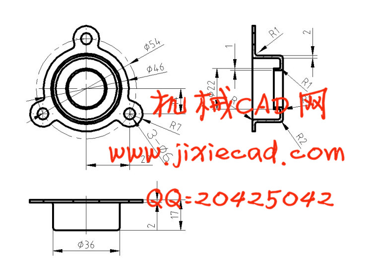
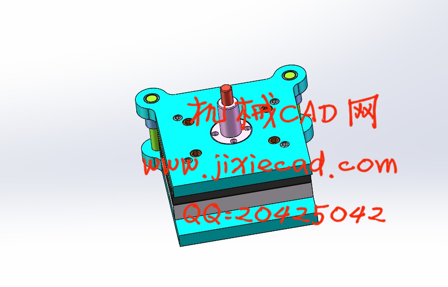
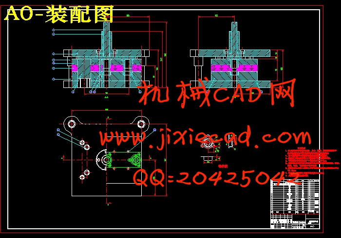
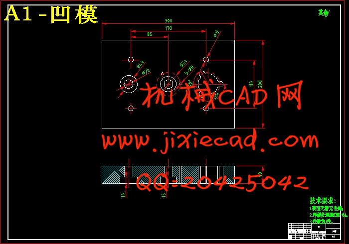
本次设计是压盖连续冲裁模的设计,制件为压盖。本文借鉴了冷冲压模具设计的全部过程。文章主要过程是从产品的工艺分析到最后设计冲压模具,首先,通过对制件的特点的了解,进一步对制件进行工艺分析,确定该制件符合冷冲压加工的要求。冲压工艺方案和结构确定为级进模具冲压,并对级进模进行设计。除对制件进行排样分析和计算搭边值、冲压力、以及确定模具压力中心外还重点分析了制件的凸模、凹模及其凸凹模结构并进行设计、计算,定位零件的选取和结构分析,以及固定方式等技术难点,最终通过AutoCAD进行绘图,得到相关零件的零件图及级进模具的装配图。关键词:冷冲压;压盖;级进模具设计
Abstract
This design is punching blanking design of the compound die, product as a convex shaped gasket. In this paper, the whole process of cold stamping die design. The article is main process from product process analysis of the final design of the stamping die, first of all, based on the understanding of the parts, parts for process analysis, to determine the work pieces with cold stamping processing requirements. Stamping process scheme and structure determination for the Flip Style compound die punching, and the design of compound die. In addition to the parts layout analysis and calculation on the boundary, pressure, and to determine the pressure center of the mould is focus on the analysis of the parts of the punch, die and punch die structure and design, calculation, selection and structure analysis of positioning component, and the fixed mode to point, finally drawing by AutoCAD the assembly diagram, parts diagram and related parts of the composite mold.
Key words: Cold stamping;convex shaped gasket;Compound die design
目 录
第一章 前言 6
1.1 我国模具行业的发展方向和前景 7
1.2 冲压加工的特点 7
1.3 冲压模具的种类 8
1.4课题意义 9
第二章 冲压工艺性分析及冲压方案的确定 10
2.1 冲压工艺性分析 10
2.2 毛坯尺寸的确定 11
2.3 冲压工艺方案的确定 11
第三章 排样设计及计算 11
3.1展开尺寸计算 12
3.2排样方案 12
3.3确定搭边值 13
3.4确定条料宽度计算利用率 13
第四章 冲裁力的计算及确定压力中心 14
4.1冲裁力的计算 14
4.2确定压力中心 15
第五章 冲裁工艺计算 16
5.1选择双面间隙 16
5.2冲裁模刃口尺寸计算原则 16
5.3冲孔和落料刃口尺寸计算 17
第六章 各零件结构尺寸 18
6.1凹模的设计 18
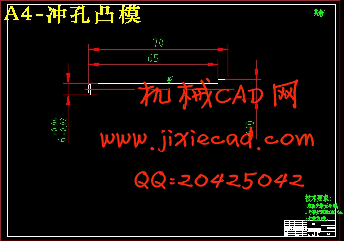
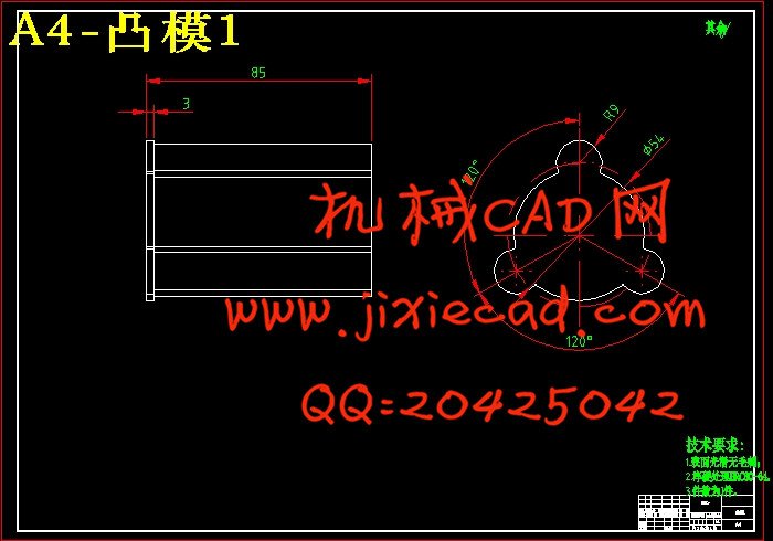
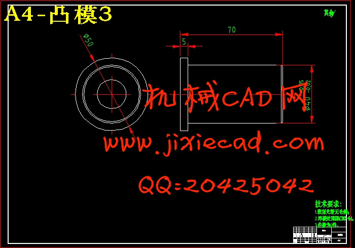
6.2凸模设计 18
6.3 凸模凹模的材料选定 19
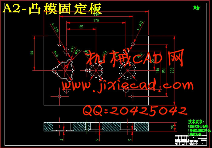
6.4 凸模固定垫板的设计 19
6.5 卸料部分的设计 19
6.5.1 卸料装置 20
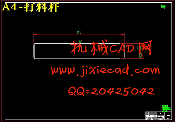
6.5.2 推件和顶件装置 20
6.5.3 橡胶的选用 21
6.6 定位部分的设计 22
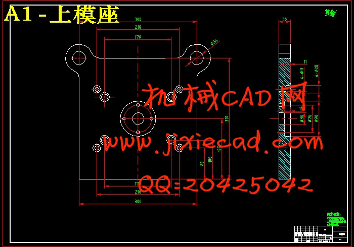
6.7 模架、模座和导柱导套 23
6.7.1 模架类型 24
6.7.2模座 25
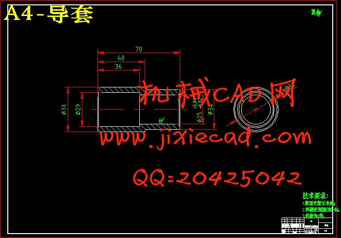
6.7.3导柱与导套的选用 26
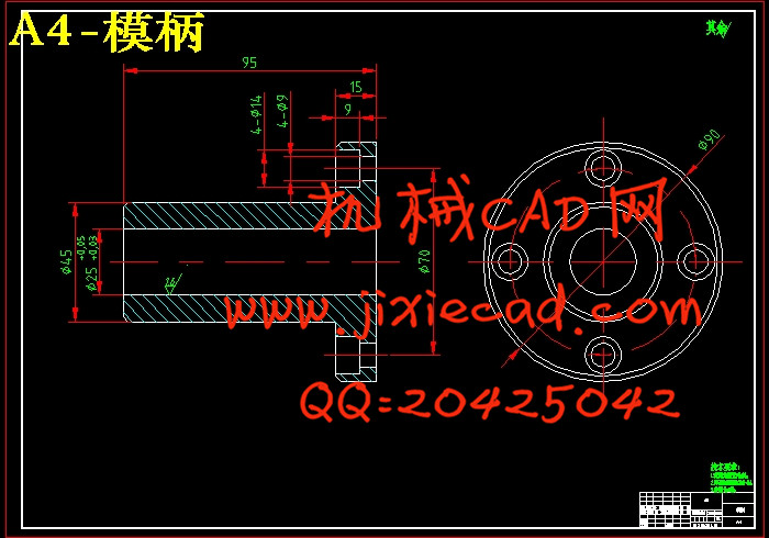
6.7.4模柄的选用 27
结论 78
参考文献 29
致 谢 30