设计简介
摘 要
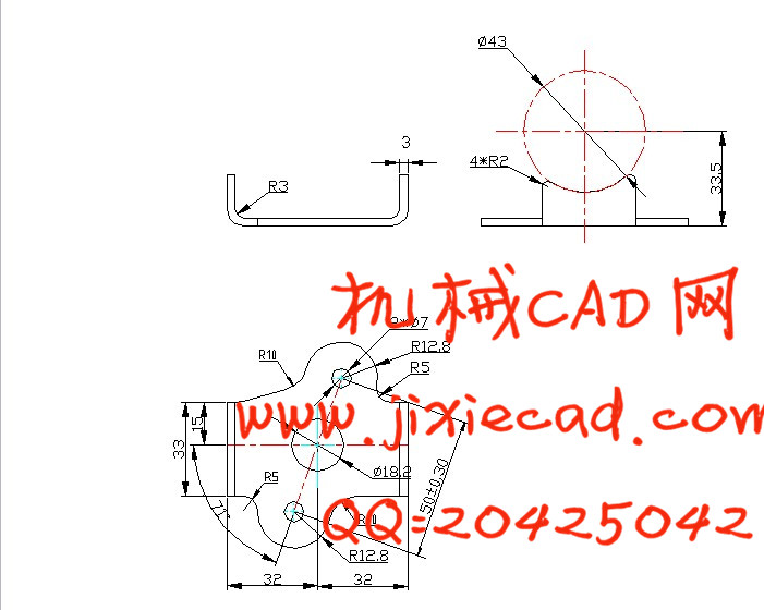
本设计主要对7702型摩托车转向锁支架冲压模具进行了设计。结合大长江公司实际生产要求和产品的特点,在厂原有的设计上,对模具进行了改进设计。本设计对摩托车转向锁支架加工工艺进行了分析,得出了最佳加工方案,在充分保证零件质量与精度的前提下,选择高生产率的加工工艺,降低生产成本,从而有效地节约了材料。本设计中使用计算机软件进行了辅助设计,在保证高精度的同时简化了传统的繁琐计算过程,使设计更为便捷。
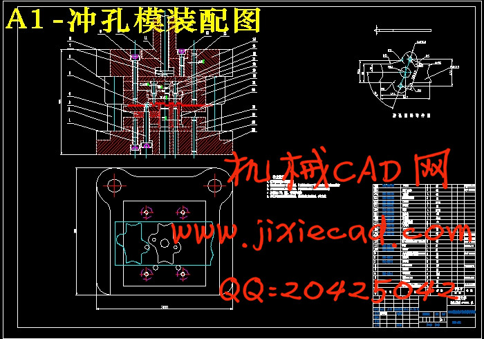
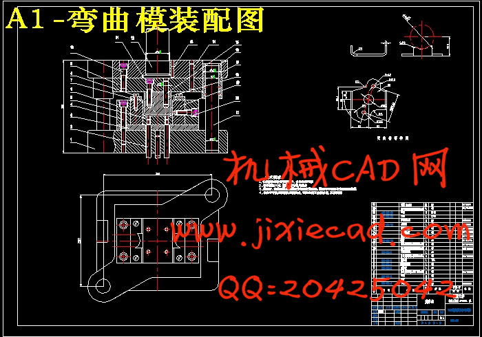
该转向锁零件从坯料到完全成形,共用到两套模具:冲孔落料复合模与弯曲模。所设计的两套模具较为典型,也具有一定的代表性。本设计的重点与难点是对凸、凹模刃口尺寸的计算,因为它将直接影响零件的质量。
关键词 冲压模具;复合模;辅助设计;模具结构
Abstract
The design mainly studies the stamping die for the nog of turning lock, 7702- motorcycle. Unite the actual production requirements and product characteristics of Great River Corporation, under the original design of the factory, carries on the innovative design to the die. The design carries on the craft analysis to the nog of turning lock, obtains the best working scheme. In the full guarantee of the component’s quality and the precision, of reducing the production cost, the high productivity processing craft is choosen. The design uses the computer-aided design software to ensure high-precision while simplifying the calculation of traditional and cumbersome process to simplify the design.
The nog of turning lock from the blanks to complete forming has two sets of mold aggregately: the punching-blanking compound die and the bending die. The two sets of molds are typical and have certain representations. The keystone and nodus of this design are the account of the knife-edge of the protrude die and the concave die as it would aflect the quality of the accessory straightly.
Key words stamping die compound die aided design die structure
目 录
摘 要 I
Abstract II
第1章 绪论 1
1.1 课题来源和研究意义 1
1.2 国内外在该方向的研究现状及分析 1
1.3 本课题研究的主要内容 2
1.4 本章小结 2
第2章 摩托车7702转向锁支架加工工艺综合分析 3
2.1 摩托车7702转向锁支架加工工艺要求 3
2.2 零件图分析 3
2.3 冲压工艺性审查 4
2.4 冲压件经济性和先进性分析 4
2.5 工艺方案的确定 4
2.6 本章小结 5
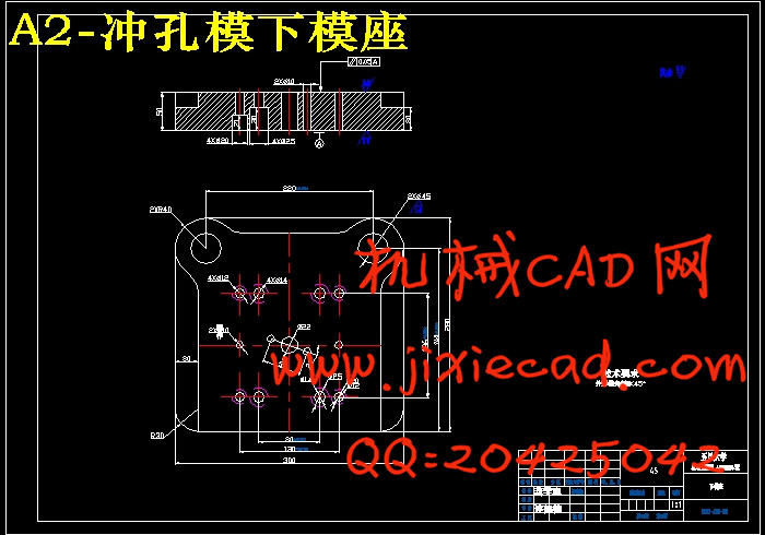
第3章 落料冲孔复合模的设计 6
3.1 冲压件的工艺分析 6
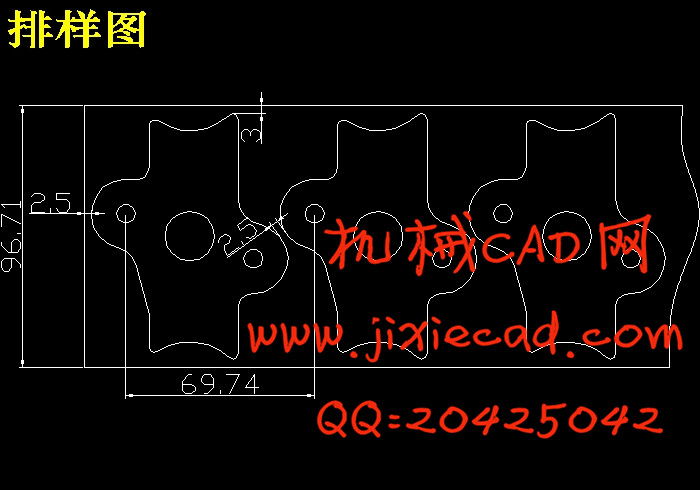
3.2 排样 6
3.3 计算冲压力 6
3.3.1 落料力 6
3.3.2 冲孔力 6
3.3.3 落料时的卸料力 7
3.3.4 冲孔时的推件力 7
3.4 确定模具压力中心 7
3.5 计算凸、凹模刃口尺寸 7
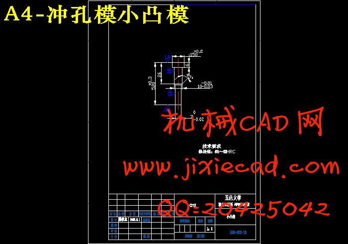
3.5.1 冲孔凸、凹模刃口计算 7
3.5.2 落料凸、凹模刃口计算 8
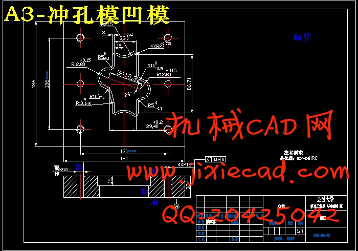
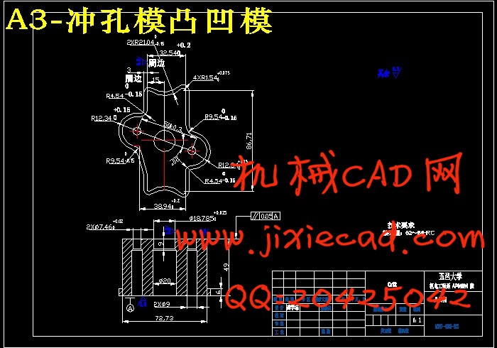
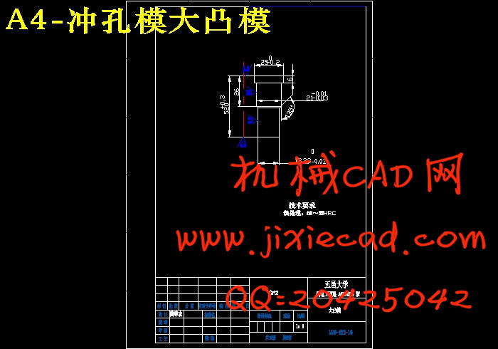
3.6 凸模、凹模、凸凹模的结构设计 9
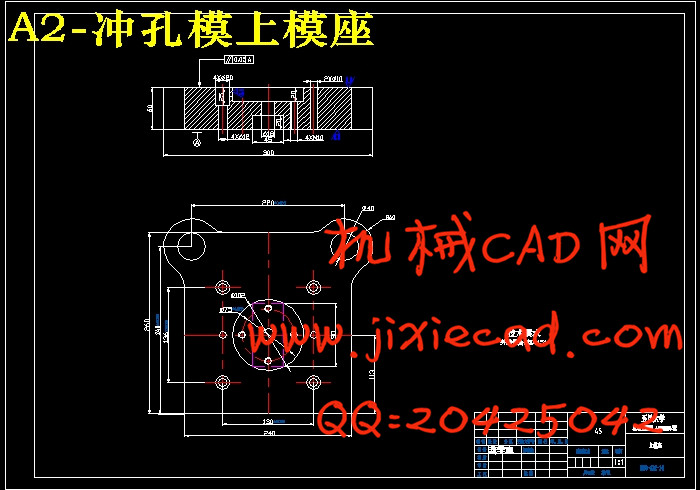
3.7 模具总体设计及主要零部件设计 11
3.7.1 模具总休装配设计 11
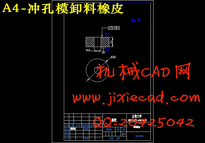
3.7.2 卸料橡皮垫的设计计算 14
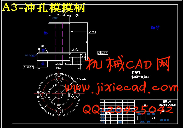
3.7.3 模柄设计 15
3.7.4 模架设计 15
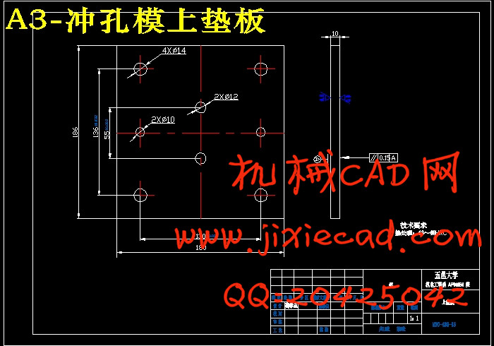
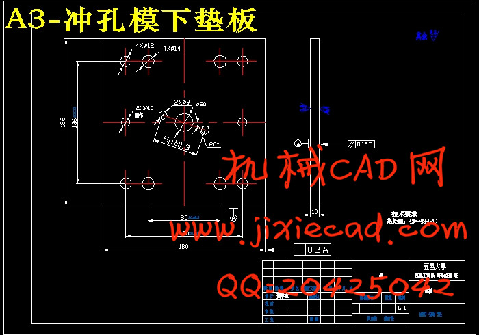
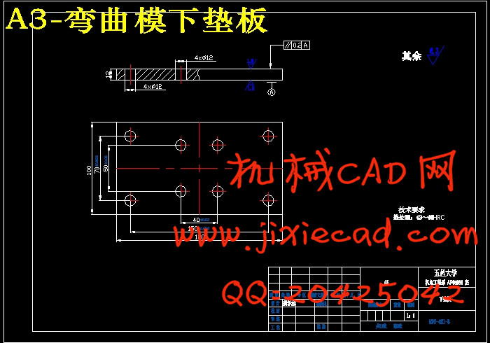
3.7.5 垫板设计 15
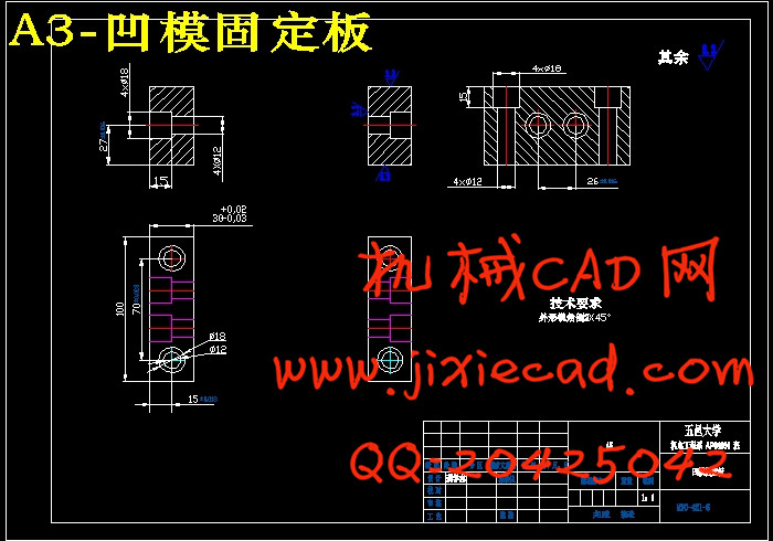
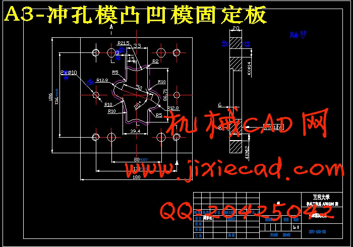
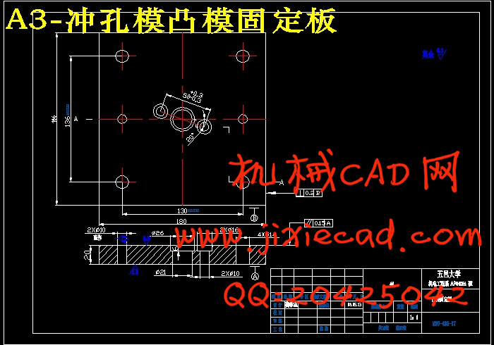
3.7.6 凸模、凸凹模固定板设计 15
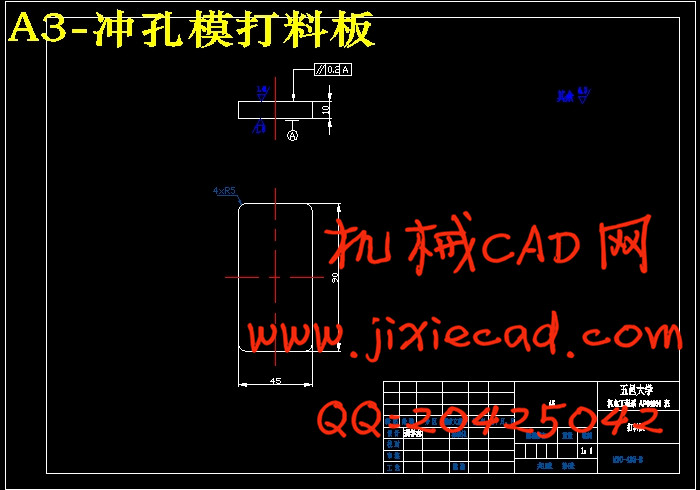
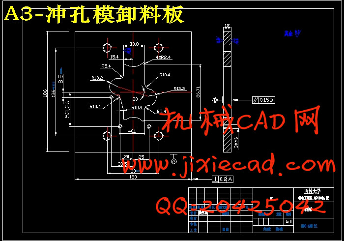
3.7.7 卸料板设计 16
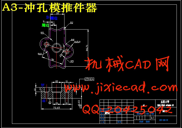
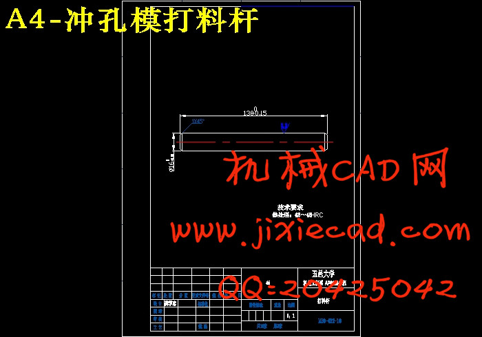
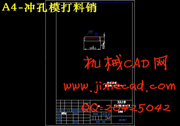
3.7.8 推件装置设计 16
3.7.9 模具的闭合高度 16
3.8 冲压设备的选择 16
3.8.1 公称压力的选择 16
3.8.2 行程次数 17
3.8.3 滑块行程(S) 17
3.8.4 闭合高度 17
3.8.5 工作台面尺寸 18
3.8.6 模柄孔尺寸 18
3.9 本章小结 18
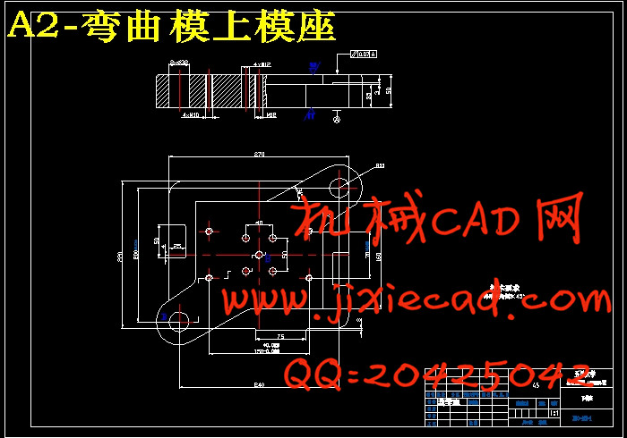
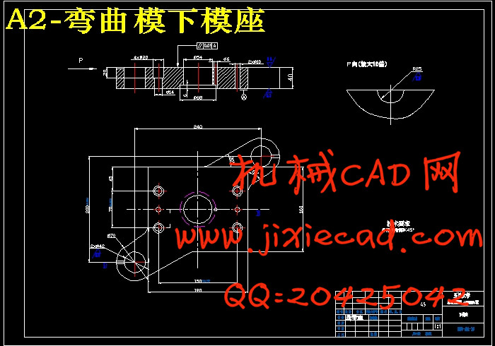
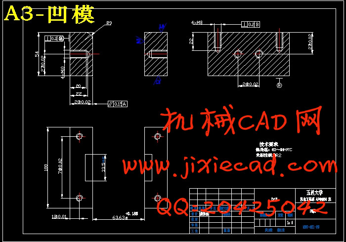
第4章 弯曲模设计 19
4.1 弯曲件工艺分析 19
4.2 弯曲工艺计算 19
4.2.1 弯曲件回弹值的计算 19
4.2.2 弯曲力的计算 20
4.3 弯曲模零件设计计算 21
4.3.1 弯曲模工作部分尺寸计算 21
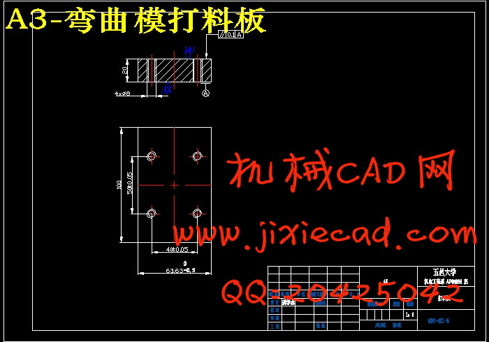
4.3.2 弯曲模其他零件的设计和选用 22
4.3.3 弯曲模闭合高度的设计计算 23
4.4 冲压设备的选择 23
4.4.1 公称压力的选择 23
4.4.2 行程次数 23
4.4.3 滑块行程(S) 24
4.4.4 模具闭合高度 24
4.4.5 工作台面尺寸 24
4.4.6 模柄孔尺寸 24
4.5 模具总装配及其零部件设计 25
4.5.1 模具总装配图设计: 25
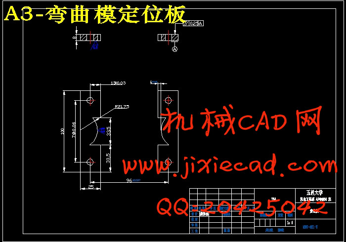
4.5.2 凹模(尺寸)设计 27
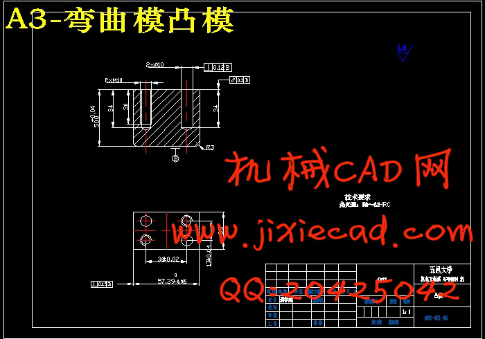
4.5.3 凸模(尺寸)设计 28
4.5.4 模架设计 28
4.5.5 凹模固定板设计 28
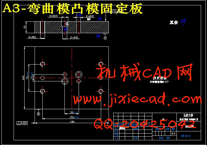
4.5.6 凸模固定板设计 28
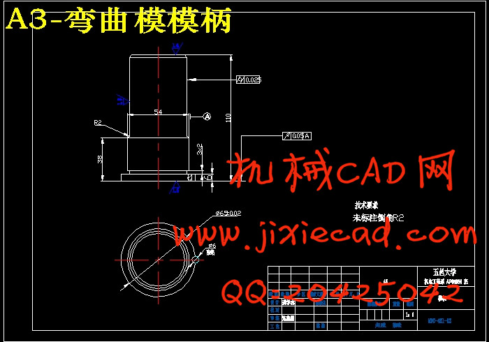
4.5.7 模柄的设计 28
4.6 本章小结 29
结 论 30
参考文献 31
致 谢 32
本设计主要对7702型摩托车转向锁支架冲压模具进行了设计。结合大长江公司实际生产要求和产品的特点,在厂原有的设计上,对模具进行了改进设计。本设计对摩托车转向锁支架加工工艺进行了分析,得出了最佳加工方案,在充分保证零件质量与精度的前提下,选择高生产率的加工工艺,降低生产成本,从而有效地节约了材料。本设计中使用计算机软件进行了辅助设计,在保证高精度的同时简化了传统的繁琐计算过程,使设计更为便捷。
该转向锁零件从坯料到完全成形,共用到两套模具:冲孔落料复合模与弯曲模。所设计的两套模具较为典型,也具有一定的代表性。本设计的重点与难点是对凸、凹模刃口尺寸的计算,因为它将直接影响零件的质量。
关键词 冲压模具;复合模;辅助设计;模具结构
Abstract
The design mainly studies the stamping die for the nog of turning lock, 7702- motorcycle. Unite the actual production requirements and product characteristics of Great River Corporation, under the original design of the factory, carries on the innovative design to the die. The design carries on the craft analysis to the nog of turning lock, obtains the best working scheme. In the full guarantee of the component’s quality and the precision, of reducing the production cost, the high productivity processing craft is choosen. The design uses the computer-aided design software to ensure high-precision while simplifying the calculation of traditional and cumbersome process to simplify the design.
The nog of turning lock from the blanks to complete forming has two sets of mold aggregately: the punching-blanking compound die and the bending die. The two sets of molds are typical and have certain representations. The keystone and nodus of this design are the account of the knife-edge of the protrude die and the concave die as it would aflect the quality of the accessory straightly.
Key words stamping die compound die aided design die structure
目 录
摘 要 I
Abstract II
第1章 绪论 1
1.1 课题来源和研究意义 1
1.2 国内外在该方向的研究现状及分析 1
1.3 本课题研究的主要内容 2
1.4 本章小结 2
第2章 摩托车7702转向锁支架加工工艺综合分析 3
2.1 摩托车7702转向锁支架加工工艺要求 3
2.2 零件图分析 3
2.3 冲压工艺性审查 4
2.4 冲压件经济性和先进性分析 4
2.5 工艺方案的确定 4
2.6 本章小结 5
第3章 落料冲孔复合模的设计 6
3.1 冲压件的工艺分析 6
3.2 排样 6
3.3 计算冲压力 6
3.3.1 落料力 6
3.3.2 冲孔力 6
3.3.3 落料时的卸料力 7
3.3.4 冲孔时的推件力 7
3.4 确定模具压力中心 7
3.5 计算凸、凹模刃口尺寸 7
3.5.1 冲孔凸、凹模刃口计算 7
3.5.2 落料凸、凹模刃口计算 8
3.6 凸模、凹模、凸凹模的结构设计 9
3.7 模具总体设计及主要零部件设计 11
3.7.1 模具总休装配设计 11
3.7.2 卸料橡皮垫的设计计算 14
3.7.3 模柄设计 15
3.7.4 模架设计 15
3.7.5 垫板设计 15
3.7.6 凸模、凸凹模固定板设计 15
3.7.7 卸料板设计 16
3.7.8 推件装置设计 16
3.7.9 模具的闭合高度 16
3.8 冲压设备的选择 16
3.8.1 公称压力的选择 16
3.8.2 行程次数 17
3.8.3 滑块行程(S) 17
3.8.4 闭合高度 17
3.8.5 工作台面尺寸 18
3.8.6 模柄孔尺寸 18
3.9 本章小结 18
第4章 弯曲模设计 19
4.1 弯曲件工艺分析 19
4.2 弯曲工艺计算 19
4.2.1 弯曲件回弹值的计算 19
4.2.2 弯曲力的计算 20
4.3 弯曲模零件设计计算 21
4.3.1 弯曲模工作部分尺寸计算 21
4.3.2 弯曲模其他零件的设计和选用 22
4.3.3 弯曲模闭合高度的设计计算 23
4.4 冲压设备的选择 23
4.4.1 公称压力的选择 23
4.4.2 行程次数 23
4.4.3 滑块行程(S) 24
4.4.4 模具闭合高度 24
4.4.5 工作台面尺寸 24
4.4.6 模柄孔尺寸 24
4.5 模具总装配及其零部件设计 25
4.5.1 模具总装配图设计: 25
4.5.2 凹模(尺寸)设计 27
4.5.3 凸模(尺寸)设计 28
4.5.4 模架设计 28
4.5.5 凹模固定板设计 28
4.5.6 凸模固定板设计 28
4.5.7 模柄的设计 28
4.6 本章小结 29
结 论 30
参考文献 31
致 谢 32