设计简介
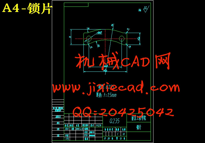
随着生产现代化程度的不断提高,人们对汽车的消费不断增加,市场对驱动桥的需求也越来越大,驱动桥产品的市场前景十分广阔。随着国内企业市场意识逐步增强,行业竞争力将不断加剧。因此,一种安全、低成本、使用寿命长的驱动桥锁片生产技术已越来越迫切。
本文对驱动桥锁片的冲压模具进行了设计,对冲压件的工艺进行了设计和计算。对模具的零件进行了设计,给出了零件图和模具装配图,最后,对模具主要零件的加工工艺进行了分析。该零件采用复合模进行加工,只需一副模具,冲压件的形状精度和尺寸精度容易保证,生产效率高。此模具不采用侧压装置,为了补偿因进料过程中条料摆动而导致的侧面搭边值的减小,条料宽度应增加一个摆动量。
本方案设计简单,结构紧凑,减少了产品制造工序,提高了零件精度。
关键词 驱动桥锁片 复合模 冲压件 摆动量
Abstract
With the continuous improvement of modern production, the consumption amount of the car is continuously increasing, and the market demand is also growing on the drive axle, the market prospect of drive axle products is very broad. With the market awareness of domestic enterprises gradually increases, the competitiveness of the industry is growing. Therefore, a safe, low-cost, long using life drive axle lock production technology has become increasingly urgent.
Stamping die of the driving axle lock is designed in this paper, stamping process of this part is designed and calculated. The parts of the mold is designed, at the same time, the parts drawing and mold assembly drawing are drawn, at last, the main parts processing technology of the mold is analyzed. The part is processed by compound modulus, just one mold, the shape and dimensional accuracy are easy to ensure, the production efficiency of the mould is high. This mold The side pressure device is not necessary in this mould, in order to compensate for side cutting-building side value of the feeding process due to the strip swing, the strip width should be increased by a swing unit.
The design of this mould is simple, and the structure is very compact, the product manufacturing process is reduced in this paper, the accuracy of parts is improved greatly.
Keywords Driving axle lock Compound mould Stamping part Swing unit
目 录
前 言 1
第一章 绪论 2
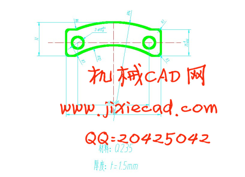
1.1产品介绍 2
1.2课题介绍 3
第二章 工艺设计 4
2.1零件的尺寸精度 4
2.2零件结构工艺分析 4
2.3冲压件的材料 4
2.4确定冲压工艺方案 4
第三章 工艺计算 6
3.1排样图设计 6
3.1.1排样的意义和材料利用率 6
3.1.2排样图确定 7
3.2刃口尺寸计算 8
3.3工艺力的计算 10
3.3.1计算总压力 10
3.3.2确定压力中心 11
3.3.3压力机的选择 12
3.3.4橡胶块的选取和尺寸的计算 13
3.4主要工作零件强度校核 13
第四章 模具设计与设备选用 14
4.1倒装式落料冲孔复合模零件相关设计 14
4.1.1工作零件的设计 14
4.1.2推件装置的设计 16
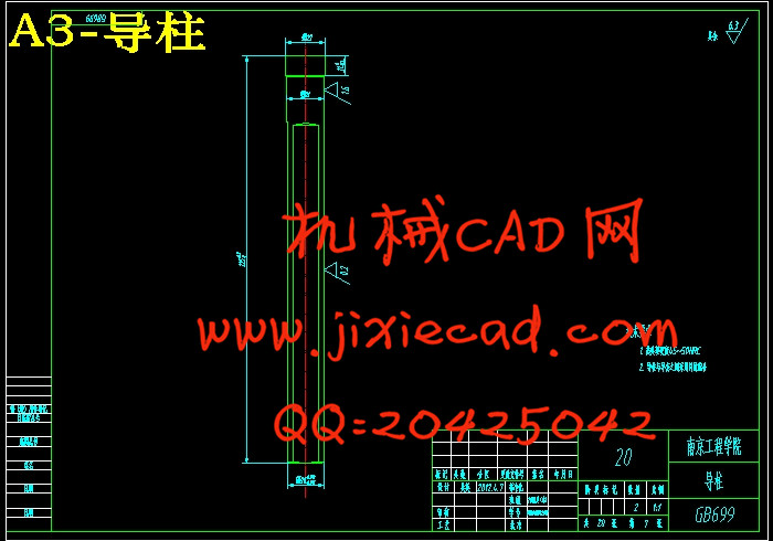
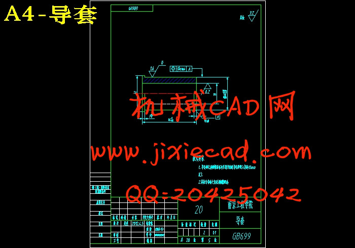
4.1.3导向零件的设计 16
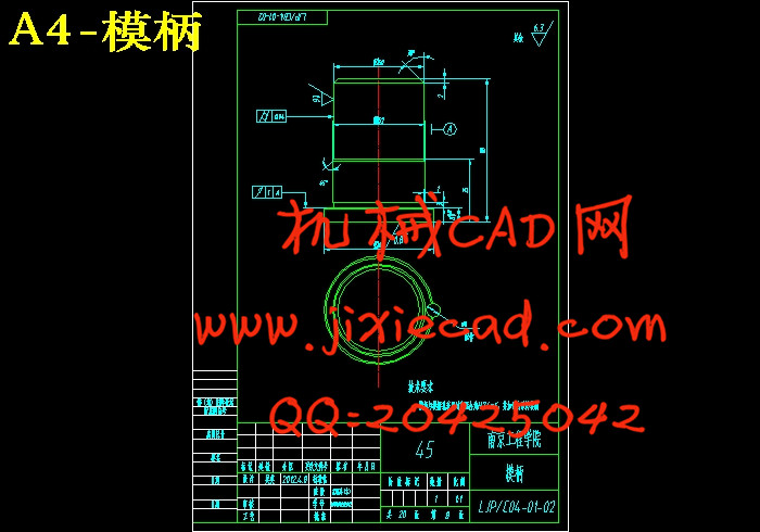
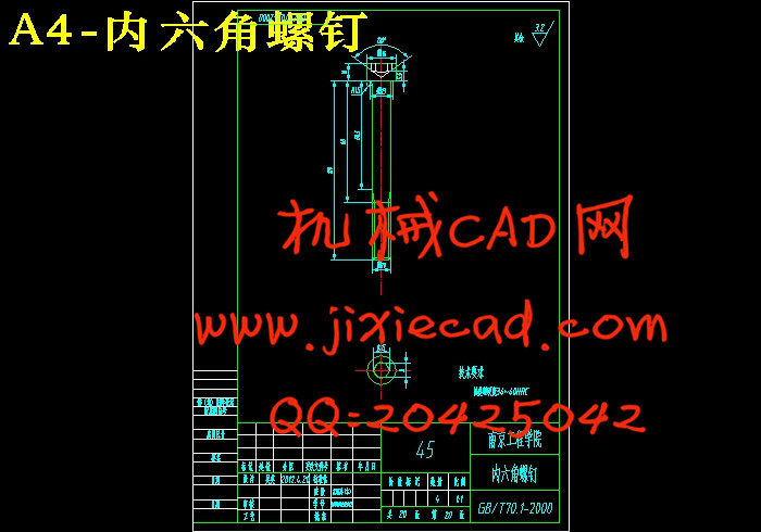
4.1.4固定零件的设计 17
4.1.5定位与卸料方式的选择 23
4.2模具总装配图的绘制与模具零件材料的选用 23
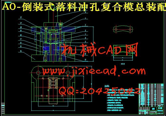
4.2.1倒装式落料冲孔复合模总装图绘制 23
4.2.2主要标准件零件的选取 24
第五章 模具制造 25
5.1主要模具零件加工工艺过程 25
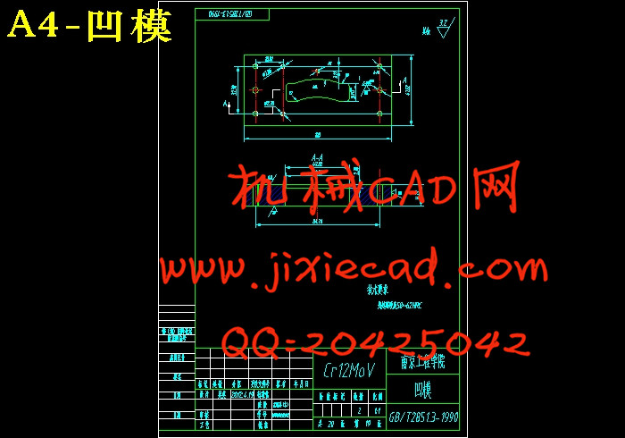
5.1.1落料凹模加工工艺过程 25
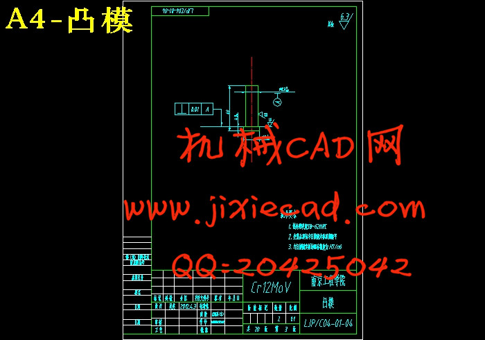
5.1.2冲孔凸模加工工艺过程 26
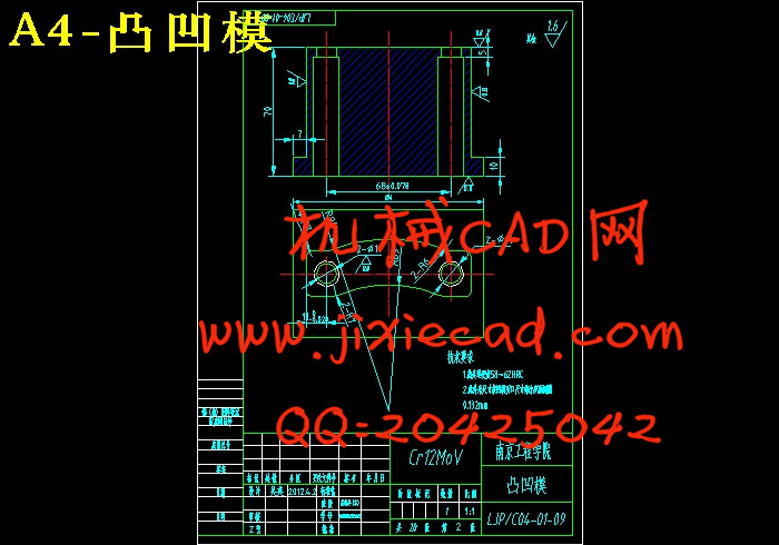
5.1.3凹凸模加工工艺过程 27
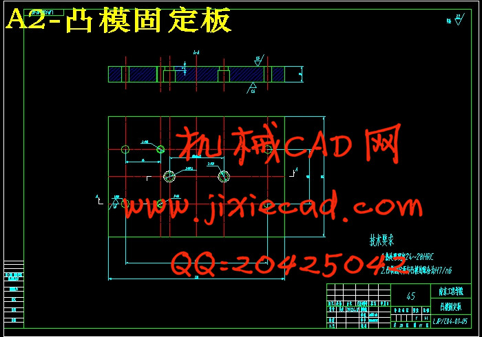
5.1.4凸模固定板加工工艺过程 28
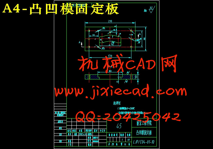
5.1.5凸凹模固定板加工工艺过程 29
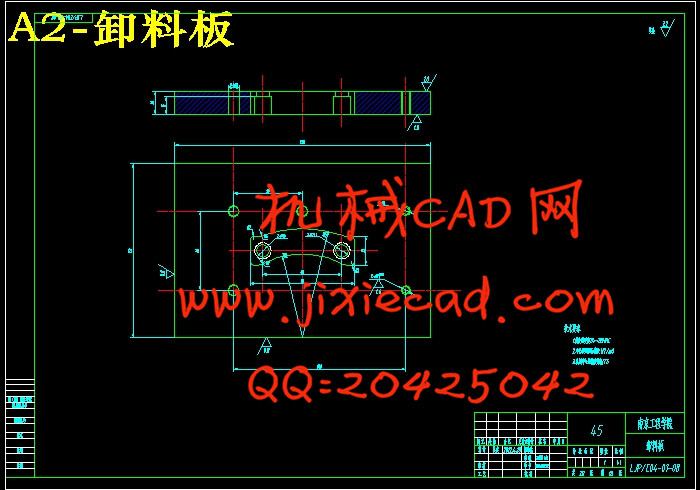
5.1.6卸料板加工工艺过程 30
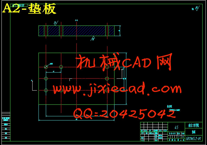
5.1.7垫板加工工艺过程 31
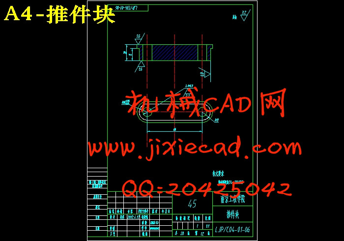
5.1.8推件块加工工艺过程 32
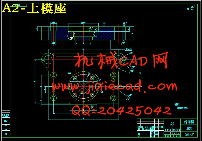
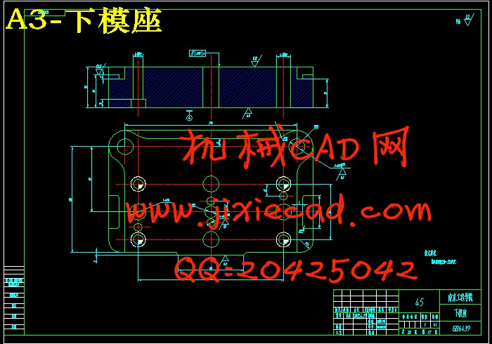
5.1.9上、下模座加工工艺过程 33
第六章 结论 34
致 谢 35
参考文献 36
本文对驱动桥锁片的冲压模具进行了设计,对冲压件的工艺进行了设计和计算。对模具的零件进行了设计,给出了零件图和模具装配图,最后,对模具主要零件的加工工艺进行了分析。该零件采用复合模进行加工,只需一副模具,冲压件的形状精度和尺寸精度容易保证,生产效率高。此模具不采用侧压装置,为了补偿因进料过程中条料摆动而导致的侧面搭边值的减小,条料宽度应增加一个摆动量。
本方案设计简单,结构紧凑,减少了产品制造工序,提高了零件精度。
关键词 驱动桥锁片 复合模 冲压件 摆动量
Abstract
With the continuous improvement of modern production, the consumption amount of the car is continuously increasing, and the market demand is also growing on the drive axle, the market prospect of drive axle products is very broad. With the market awareness of domestic enterprises gradually increases, the competitiveness of the industry is growing. Therefore, a safe, low-cost, long using life drive axle lock production technology has become increasingly urgent.
Stamping die of the driving axle lock is designed in this paper, stamping process of this part is designed and calculated. The parts of the mold is designed, at the same time, the parts drawing and mold assembly drawing are drawn, at last, the main parts processing technology of the mold is analyzed. The part is processed by compound modulus, just one mold, the shape and dimensional accuracy are easy to ensure, the production efficiency of the mould is high. This mold The side pressure device is not necessary in this mould, in order to compensate for side cutting-building side value of the feeding process due to the strip swing, the strip width should be increased by a swing unit.
The design of this mould is simple, and the structure is very compact, the product manufacturing process is reduced in this paper, the accuracy of parts is improved greatly.
Keywords Driving axle lock Compound mould Stamping part Swing unit
目 录
前 言 1
第一章 绪论 2
1.1产品介绍 2
1.2课题介绍 3
第二章 工艺设计 4
2.1零件的尺寸精度 4
2.2零件结构工艺分析 4
2.3冲压件的材料 4
2.4确定冲压工艺方案 4
第三章 工艺计算 6
3.1排样图设计 6
3.1.1排样的意义和材料利用率 6
3.1.2排样图确定 7
3.2刃口尺寸计算 8
3.3工艺力的计算 10
3.3.1计算总压力 10
3.3.2确定压力中心 11
3.3.3压力机的选择 12
3.3.4橡胶块的选取和尺寸的计算 13
3.4主要工作零件强度校核 13
第四章 模具设计与设备选用 14
4.1倒装式落料冲孔复合模零件相关设计 14
4.1.1工作零件的设计 14
4.1.2推件装置的设计 16
4.1.3导向零件的设计 16
4.1.4固定零件的设计 17
4.1.5定位与卸料方式的选择 23
4.2模具总装配图的绘制与模具零件材料的选用 23
4.2.1倒装式落料冲孔复合模总装图绘制 23
4.2.2主要标准件零件的选取 24
第五章 模具制造 25
5.1主要模具零件加工工艺过程 25
5.1.1落料凹模加工工艺过程 25
5.1.2冲孔凸模加工工艺过程 26
5.1.3凹凸模加工工艺过程 27
5.1.4凸模固定板加工工艺过程 28
5.1.5凸凹模固定板加工工艺过程 29
5.1.6卸料板加工工艺过程 30
5.1.7垫板加工工艺过程 31
5.1.8推件块加工工艺过程 32
5.1.9上、下模座加工工艺过程 33
第六章 结论 34
致 谢 35
参考文献 36