设计简介
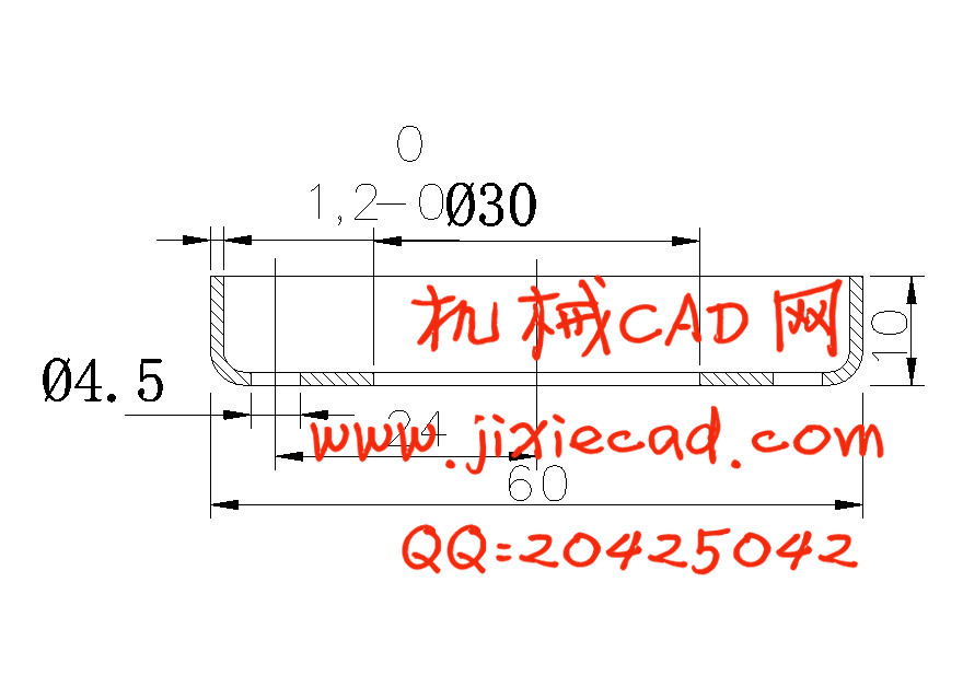
上防尘盖冲压工艺及模具设计
摘 要
本次设计是对上防尘盖冲孔模具设计的要求,分别对模具的工作零部件等六大类零部件作详细设计。设计的主要内容包括冲裁件的工艺分析及工艺方案的确定、工艺计算、冲裁模具的设计、模具的安装与调整等。
在工艺计算部分要对冲压力的计算、模具压力中心的确定、凸凹模尺寸并确定制造公差的计算、弹性元件的选取与计算等内容详细计算。必要时还要对模具的主要零件进行强度验算。
在冲裁模的设计部分要对工作零件、定位零件、卸料与顶件零件、导向零件连接与固定零件等结构进行详细的分析设计。要在设计过程中了解模具的工作过程和注意标准的选用,对单工序冲裁模的结构有进一步的了解。
模具的安装与调试部分要注意有导柱模具与无导柱模具的安装方法及顺序,通过模具的安装,了解模具的组成及各部分零部件的作用等。注意模具安装过后的试冲过程中常见的缺陷与解决方法等。
通过这次毕业设计要对单工序模具有更近一步的了解,注意它与复合模和级进模之间的区别,三者虽然都是一副模具,但本次单工序模是单存的冲孔,在设计时要注意模具结构简单、模具使用方便、模具寿命高等问题。并且要提高生产效率,保证产品的质量。
关键词:复合模 级进模 试冲 间隙配合 过渡配合
On dust cap ramming craft and mold design
Abstract
This graduation project is the request which designs to on dust cap punch holes mold,Separately and so on six big kind of spare parts makes the detailed design to the mold work spare part. Design primary coverage including blanking craft analysis and craft plan determination, process design, blanking mold design, mold installment and adjustment and so on.
n the process design part must to the ramming strength computation, the mold center of pressure determination, the convex-concave mold size and determines the manufacture common difference content detailed computations and so on computation, elastic part selection and computation。When necessity also must carry on the intensity checking calculation to the mold major parts.
In the punching die design part must to the work components, the localization components, the ex-denning and goes against components, the guidance components connection and fixed components isostructuralism carries on the detailed analysis design.。Must understand the mold in the design process the work process and attention standard selection,Has the further understanding to the single working procedure punching die structure.
The mold installment and the debugging part must pay attention have the guide pillar mold to install the method and the order with the non-guide pillar mold,Through mold installment,Understands the mold the composition and various part of spare part function and so on. The attention mold installment from now on will try to flush in the process the common flaw and the solution and so on。
Must have a nearer step understanding through this graduation project to the single working procedure mold,Pays attention to it enters between the mold with the superposable die and the level the difference,Three although all is a mold,But this single working procedure mold is Shan Cun the punch holes,When design must pay attention to the mold structure simply, the mold easy to operate, the mold life higher question. And must enhance the production efficiency,Guarantees the product the quality.
Key word:Superposable die The level enters the mold Tries to flush Gap coordination Transition fit
目录
第1章 绪论………………………………………………………………………..2
第2章 冲裁工艺设计…………………………………………………………….3
2.1 冲压工艺......................................................3
2.1.1 冲压工艺设计..........................................3
2.1.2 冲裁件的工艺性........................................3
2.1.3 冲裁件的工艺性分析....................................3
2.2 工艺方案的确定................................................3
2.2.1 冲裁件的工艺方案分析..................................3
第3章 工艺计算………………………………………………………………….4
3.1 冲压力的计算..................................................4
3.1.1 冲裁力的计算..........................................4
3.1.2 卸料力、推件力、顶件力的计算..........................4
3.1.3 总压力计算............................................5
3.2 压力中心的确定................................................5
3.2.1 压力中心的计算........................................5
第4章 模具结构及成形设备的选择………….................................................7
4.1 模具结构的确定................................................7
4.1.1 模具结构的选择........................................7
4.2 冲压设备的确定................................................7
4.2.1 冲压设备的选择........................................7
第5章 主要模具结构的设计及校核…………………………………………8
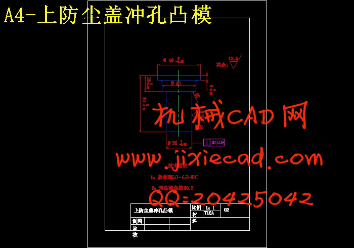
5.1 凸模的设计....................................................8
5.1.1 凸模的结构设计........................................8
5.1.2 凸模长度的设计........................................8
5.1.3 凸模材料及其他要求....................................8
5.2 凸模的强度与刚度的校核.......................................9
5.2.1 正压力的校核..........................................9
5.2.2 弯曲应力的校核........................................9
5.2.3 凸模固定端的压力校核.................................10
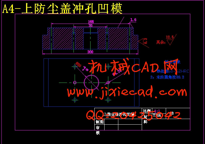
5.3 凹模的结构设计..............................................11
5.3.1 凹模刃口的结构形式...................................11
5.3.2 凹模外形尺寸的确定...................................11
5.4 工作部分尺寸刃口的计算......................................11
5.4.1 凸模、凹模间隙.......................................11
5.4.2 凹模刃口计算.........................................12
第6章 其它零部件的选择……………………………………………………….13
6.1 定位装置的选择...............................................13
6.1.1 定位零部件的选择.....................................13
6.1.2 定位板的设计.........................................13
6.2 卸料装置的选择..............................................13
6.2.1 卸料零部件的设计.....................................13
6.3 导向装置的选择...............................................13
6.3.1 导向方式的选择.......................................13
6.4 连接与固定零件的选择........................................14
6.4.1 模柄的选择...........................................14
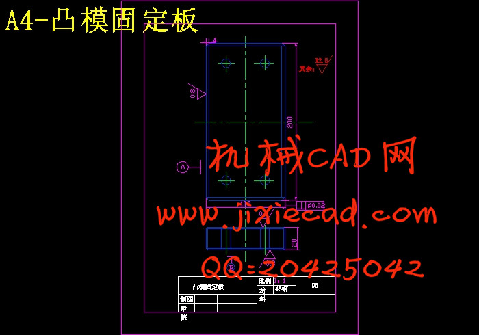
6.4.2 固定板的选择.........................................14
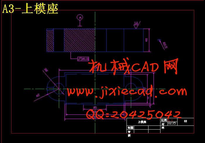
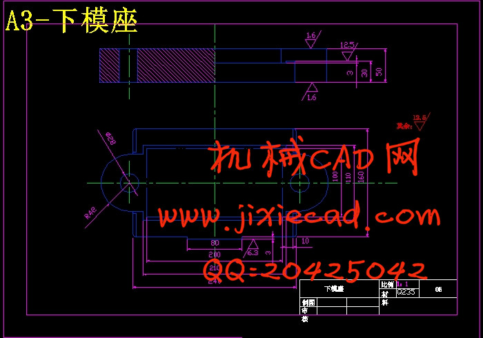
6.4.3 上模座、下模座的选择.................................15
6.5 标准件的选择................................................15
6.5.1 模架的选用...........................................15
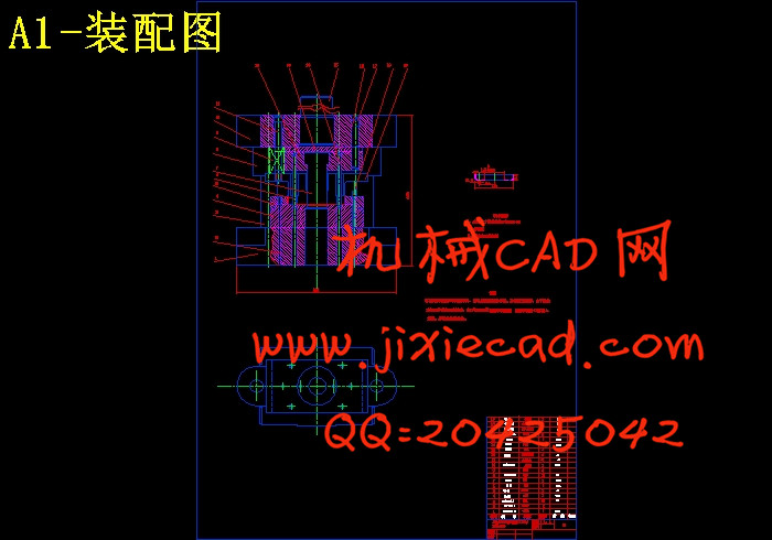
第7章 模具的装配与调试……………………………………………..17
7.1 模具的装配...................................................17
7.1.1 模具的装配要点.......................................17
7.1.2 模具的装配...........................................17
7.2 模具的调试..................................................18
7.2.1 调整模具闭合高度.....................................18
7.2.2 调整冲裁间隙.........................................18
7.3 试模与模具的运动过程........................................18
7.3.1 模具的试模...........................................18
7.3.2 模具的运动过程.......................................19
计总结……………………………………………………………………………….20
考文献……………………………………………………………………………….21
致谢………………………………………………………………………………….22
摘 要
本次设计是对上防尘盖冲孔模具设计的要求,分别对模具的工作零部件等六大类零部件作详细设计。设计的主要内容包括冲裁件的工艺分析及工艺方案的确定、工艺计算、冲裁模具的设计、模具的安装与调整等。
在工艺计算部分要对冲压力的计算、模具压力中心的确定、凸凹模尺寸并确定制造公差的计算、弹性元件的选取与计算等内容详细计算。必要时还要对模具的主要零件进行强度验算。
在冲裁模的设计部分要对工作零件、定位零件、卸料与顶件零件、导向零件连接与固定零件等结构进行详细的分析设计。要在设计过程中了解模具的工作过程和注意标准的选用,对单工序冲裁模的结构有进一步的了解。
模具的安装与调试部分要注意有导柱模具与无导柱模具的安装方法及顺序,通过模具的安装,了解模具的组成及各部分零部件的作用等。注意模具安装过后的试冲过程中常见的缺陷与解决方法等。
通过这次毕业设计要对单工序模具有更近一步的了解,注意它与复合模和级进模之间的区别,三者虽然都是一副模具,但本次单工序模是单存的冲孔,在设计时要注意模具结构简单、模具使用方便、模具寿命高等问题。并且要提高生产效率,保证产品的质量。
关键词:复合模 级进模 试冲 间隙配合 过渡配合
On dust cap ramming craft and mold design
Abstract
This graduation project is the request which designs to on dust cap punch holes mold,Separately and so on six big kind of spare parts makes the detailed design to the mold work spare part. Design primary coverage including blanking craft analysis and craft plan determination, process design, blanking mold design, mold installment and adjustment and so on.
n the process design part must to the ramming strength computation, the mold center of pressure determination, the convex-concave mold size and determines the manufacture common difference content detailed computations and so on computation, elastic part selection and computation。When necessity also must carry on the intensity checking calculation to the mold major parts.
In the punching die design part must to the work components, the localization components, the ex-denning and goes against components, the guidance components connection and fixed components isostructuralism carries on the detailed analysis design.。Must understand the mold in the design process the work process and attention standard selection,Has the further understanding to the single working procedure punching die structure.
The mold installment and the debugging part must pay attention have the guide pillar mold to install the method and the order with the non-guide pillar mold,Through mold installment,Understands the mold the composition and various part of spare part function and so on. The attention mold installment from now on will try to flush in the process the common flaw and the solution and so on。
Must have a nearer step understanding through this graduation project to the single working procedure mold,Pays attention to it enters between the mold with the superposable die and the level the difference,Three although all is a mold,But this single working procedure mold is Shan Cun the punch holes,When design must pay attention to the mold structure simply, the mold easy to operate, the mold life higher question. And must enhance the production efficiency,Guarantees the product the quality.
Key word:Superposable die The level enters the mold Tries to flush Gap coordination Transition fit
目录
第1章 绪论………………………………………………………………………..2
第2章 冲裁工艺设计…………………………………………………………….3
2.1 冲压工艺......................................................3
2.1.1 冲压工艺设计..........................................3
2.1.2 冲裁件的工艺性........................................3
2.1.3 冲裁件的工艺性分析....................................3
2.2 工艺方案的确定................................................3
2.2.1 冲裁件的工艺方案分析..................................3
第3章 工艺计算………………………………………………………………….4
3.1 冲压力的计算..................................................4
3.1.1 冲裁力的计算..........................................4
3.1.2 卸料力、推件力、顶件力的计算..........................4
3.1.3 总压力计算............................................5
3.2 压力中心的确定................................................5
3.2.1 压力中心的计算........................................5
第4章 模具结构及成形设备的选择………….................................................7
4.1 模具结构的确定................................................7
4.1.1 模具结构的选择........................................7
4.2 冲压设备的确定................................................7
4.2.1 冲压设备的选择........................................7
第5章 主要模具结构的设计及校核…………………………………………8
5.1 凸模的设计....................................................8
5.1.1 凸模的结构设计........................................8
5.1.2 凸模长度的设计........................................8
5.1.3 凸模材料及其他要求....................................8
5.2 凸模的强度与刚度的校核.......................................9
5.2.1 正压力的校核..........................................9
5.2.2 弯曲应力的校核........................................9
5.2.3 凸模固定端的压力校核.................................10
5.3 凹模的结构设计..............................................11
5.3.1 凹模刃口的结构形式...................................11
5.3.2 凹模外形尺寸的确定...................................11
5.4 工作部分尺寸刃口的计算......................................11
5.4.1 凸模、凹模间隙.......................................11
5.4.2 凹模刃口计算.........................................12
第6章 其它零部件的选择……………………………………………………….13
6.1 定位装置的选择...............................................13
6.1.1 定位零部件的选择.....................................13
6.1.2 定位板的设计.........................................13
6.2 卸料装置的选择..............................................13
6.2.1 卸料零部件的设计.....................................13
6.3 导向装置的选择...............................................13
6.3.1 导向方式的选择.......................................13
6.4 连接与固定零件的选择........................................14
6.4.1 模柄的选择...........................................14
6.4.2 固定板的选择.........................................14
6.4.3 上模座、下模座的选择.................................15
6.5 标准件的选择................................................15
6.5.1 模架的选用...........................................15
第7章 模具的装配与调试……………………………………………..17
7.1 模具的装配...................................................17
7.1.1 模具的装配要点.......................................17
7.1.2 模具的装配...........................................17
7.2 模具的调试..................................................18
7.2.1 调整模具闭合高度.....................................18
7.2.2 调整冲裁间隙.........................................18
7.3 试模与模具的运动过程........................................18
7.3.1 模具的试模...........................................18
7.3.2 模具的运动过程.......................................19
计总结……………………………………………………………………………….20
考文献……………………………………………………………………………….21
致谢………………………………………………………………………………….22